
Information Update
Page 11
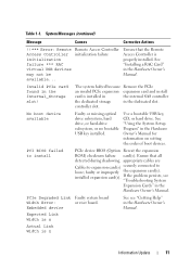
...System Setup Program" in the Hardware Owner's Manual. PCIe Degraded Link Faulty system board Width Error: or riser board. installed expansion card(s). System Messages (continued) Message Causes Corrective Actions !!*** Error: Remote Access Controller initialization failure *** RAC virtual ...USB devices may not be available... Embedded device See see "Troubleshooting System Expansion Cards" in the Hardware Owner's Manual. Expected Link Width is n Actual Link Width is properly installed. Ensure that the...
...System Setup Program" in the Hardware Owner's Manual. PCIe Degraded Link Faulty system board Width Error: or riser board. installed expansion card(s). System Messages (continued) Message Causes Corrective Actions !!*** Error: Remote Access Controller initialization failure *** RAC virtual ...USB devices may not be available... Embedded device See see "Troubleshooting System Expansion Cards" in the Hardware Owner's Manual. Expected Link Width is n Actual Link Width is properly installed. Ensure that the...

Information Update
Page 12
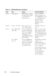
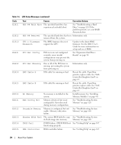
... Link Width is n Actual Link Width is n Reseat the PCIe card in the Hardware Owner's Manual. See "Expansion Cards" in the Hardware Owner's Manual. PCIe Training Error: Embedded device Faulty system board or riser board. If the problem persists, see "Getting Help" in the ... improperly installed. See "Installing a SAS Controller Daughter Card" in the dedicated PCIe connector. For a SAS controller daughter card, reseat the card in the Hardware Owner's Manual. PCIe Degraded Link Faulty system board Width Error: Slot n or riser board. If the problem persists, see "Getting Help...
... Link Width is n Actual Link Width is n Reseat the PCIe card in the Hardware Owner's Manual. See "Expansion Cards" in the Hardware Owner's Manual. PCIe Training Error: Embedded device Faulty system board or riser board. If the problem persists, see "Getting Help" in the ... improperly installed. See "Installing a SAS Controller Daughter Card" in the dedicated PCIe connector. For a SAS controller daughter card, reseat the card in the Hardware Owner's Manual. PCIe Degraded Link Faulty system board Width Error: Slot n or riser board. If the problem persists, see "Getting Help...
Information Update
Page 16
...slot. The system BIOS has reported a PCI parity error on a component that resides in the Hardware Owner's Manual. Reinstall the expansioncard riser. See "Getting Help" in the Hardware Owner's Manual. Table 1-2. LCD Status Messages (continued) Code E1211 Text ROMB Batt Causes RAID...of acceptable range. Check the AC power source. See "Expansion Card Risers" in the Hardware Owner's Manual. 16 Information Update Corrective Actions Reseat the RAID battery connector. If the problem persists, the riser card or system board is faulty. Remove and reseat the PCIe ...
...slot. The system BIOS has reported a PCI parity error on a component that resides in the Hardware Owner's Manual. Reinstall the expansioncard riser. See "Getting Help" in the Hardware Owner's Manual. Table 1-2. LCD Status Messages (continued) Code E1211 Text ROMB Batt Causes RAID...of acceptable range. Check the AC power source. See "Expansion Card Risers" in the Hardware Owner's Manual. 16 Information Update Corrective Actions Reseat the RAID battery connector. If the problem persists, the riser card or system board is faulty. Remove and reseat the PCIe ...
Information Update
Page 17
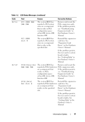
...The system BIOS has Remove and reseat the reported a PCIe fatal error PCIe expansion cards. PCIE Fatal Err Slot # The system BIOS has Reinstall the expansion- If the problem persists, the riser card or system board is faulty. Table 1-2. Manual. Information Update 17 LCD Status ... ##, device ##, function ##. Owner's Manual. If the problem persists, the riser card or system board is faulty. on a component that If the problem persists, resides in PCIe see "Troubleshooting Expansion Cards" in the Hardware slot. See "Getting Help" in the Hardware Owner's Manual...
...The system BIOS has Remove and reseat the reported a PCIe fatal error PCIe expansion cards. PCIE Fatal Err Slot # The system BIOS has Reinstall the expansion- If the problem persists, the riser card or system board is faulty. Table 1-2. Manual. Information Update 17 LCD Status ... ##, device ##, function ##. Owner's Manual. If the problem persists, the riser card or system board is faulty. on a component that If the problem persists, resides in PCIe see "Troubleshooting Expansion Cards" in the Hardware slot. See "Getting Help" in the Hardware Owner's Manual...
Getting Started Guide
Page 6
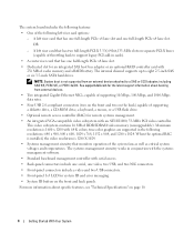
...data rates. • Four USB 2.0-compliant connectors (two on the front and two on page 10. 4 Getting Started With Your System See support.dell.com for the latest support information about specific features, see "Technical Specifications" on the back) capable of supporting a diskette drive, a CD-ROM ...attached to a SAS or SCSI adapter, including SAS 5/E, PERC 5/E, or PERC 4e/DC. OR - A left riser card options: - The systems management circuitry works in cards). • A center riser card that has two full-length PCI-X 3.3-V, 64-bit,133-MHz slots on the front and back panels. This ...
...data rates. • Four USB 2.0-compliant connectors (two on the front and two on page 10. 4 Getting Started With Your System See support.dell.com for the latest support information about specific features, see "Technical Specifications" on the back) capable of supporting a diskette drive, a CD-ROM ...attached to a SAS or SCSI adapter, including SAS 5/E, PERC 5/E, or PERC 4e/DC. OR - A left riser card options: - The systems management circuitry works in cards). • A center riser card that has two full-length PCI-X 3.3-V, 64-bit,133-MHz slots on the front and back panels. This ...
Hardware Owner's Manual (PDF)
Page 6
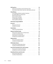
... a Processor 93 Installing a Processor 95 System Battery 96 Replacing the System Battery 96 Expansion-Card Riser Boards 98 Removing the Left Expansion-Card Riser Board 98 Installing the Left Riser Board 99 Removing the Central Riser Board 100 Installing the Central Riser Board 100 Sideplane Board 101 Removing the Sideplane Board 101 Installing the Sideplane Board 102...
... a Processor 93 Installing a Processor 95 System Battery 96 Replacing the System Battery 96 Expansion-Card Riser Boards 98 Removing the Left Expansion-Card Riser Board 98 Installing the Left Riser Board 99 Removing the Central Riser Board 100 Installing the Central Riser Board 100 Sideplane Board 101 Removing the Sideplane Board 101 Installing the Sideplane Board 102...

Hardware Owner's Manual (PDF)
Page 8
... and Connectors 135 System Board Jumpers 135 System Board Connectors 137 SAS Backplane Board Connectors 139 Sideplane Board Connectors 142 Expansion-Card Riser-Board Components and PCI Buses 142 Disabling a Forgotten Password 144 7 Getting Help 147 Technical Assistance 147 Online Services 147 ...AutoTech Service 148 Automated Order-Status Service 148 Technical Support Service 148 Dell Enterprise Training and Certification 149 Problems With Your Order 149 Product Information 149 Returning Items for Warranty Repair or Credit 149 ...
... and Connectors 135 System Board Jumpers 135 System Board Connectors 137 SAS Backplane Board Connectors 139 Sideplane Board Connectors 142 Expansion-Card Riser-Board Components and PCI Buses 142 Disabling a Forgotten Password 144 7 Getting Help 147 Technical Assistance 147 Online Services 147 ...AutoTech Service 148 Automated Order-Status Service 148 Technical Support Service 148 Dell Enterprise Training and Certification 149 Problems With Your Order 149 Product Information 149 Returning Items for Warranty Repair or Credit 149 ...

Hardware Owner's Manual (PDF)
Page 23
... the specified slot. Unknown Err The system BIOS has determined that resides in the system, but is faulty. If the problem persists, the riser card or system board is faulty. The system BIOS has reported a See "Expansion-Card Cage" on PCI system error on page 147. If the problem persists, see "Troubleshooting Expansion...
... the specified slot. Unknown Err The system BIOS has determined that resides in the system, but is faulty. If the problem persists, the riser card or system board is faulty. The system BIOS has reported a See "Expansion-Card Cage" on PCI system error on page 147. If the problem persists, see "Troubleshooting Expansion...
Hardware Owner's Manual (PDF)
Page 24
...prevent the system from the system. See "Troubleshooting System Memory" on page 124. CMOS Fail CMOS failure. functioning properly. See "Expansion-Card Riser Boards" on page 120. SAS Cable B SAS cable B is missing, preventing the system from powering on. DMA Controller DMA controller...See "Troubleshooting System its flash image into memory. See the BMC User's Guide for more information on . PCI Rsr Config PCI risers are not configured correctly; Information only. SAS Cable A SAS cable A is installed in the system. Reseat the cable. Reseat ...
...prevent the system from the system. See "Troubleshooting System Memory" on page 124. CMOS Fail CMOS failure. functioning properly. See "Expansion-Card Riser Boards" on page 120. SAS Cable B SAS cable B is missing, preventing the system from powering on. DMA Controller DMA controller...See "Troubleshooting System its flash image into memory. See the BMC User's Guide for more information on . PCI Rsr Config PCI risers are not configured correctly; Information only. SAS Cable A SAS cable A is installed in the system. Reseat the cable. Reseat ...

Hardware Owner's Manual (PDF)
Page 26
... present, the "Crd #" string is left out of the message. If no memory riser card is present, the "Crd #" string is rebooted. "## & ##" represents the DIMM pair implicated by the BIOS. Intrusion System cover has been removed. Check the SEL for ... See "Troubleshooting System memory because it has determined that the memory had too many errors. See "Troubleshooting System Memory" on page 120. If no memory card is present, the "Crd #" string is left out of three error events. the Southbound side has failed. logging, and will not resume logging further SBEs...
... present, the "Crd #" string is left out of the message. If no memory riser card is present, the "Crd #" string is rebooted. "## & ##" represents the DIMM pair implicated by the BIOS. Intrusion System cover has been removed. Check the SEL for ... See "Troubleshooting System memory because it has determined that the memory had too many errors. See "Troubleshooting System Memory" on page 120. If no memory card is present, the "Crd #" string is left out of three error events. the Southbound side has failed. logging, and will not resume logging further SBEs...

Hardware Owner's Manual (PDF)
Page 51
...; System fans • Cooling shroud • Fan brackets • SAS controller daughter card • RAID battery • Expansion cards • Expansion card cage • RAC card • Optical, diskette, and tape drives • System memory • Processors • System battery • Expansion-card riser boards • Sideplane board • SAS Backplane board • Control panel assembly...
...; System fans • Cooling shroud • Fan brackets • SAS controller daughter card • RAID battery • Expansion cards • Expansion card cage • RAC card • Optical, diskette, and tape drives • System memory • Processors • System battery • Expansion-card riser boards • Sideplane board • SAS Backplane board • Control panel assembly...
Hardware Owner's Manual (PDF)
Page 52
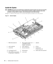
... inside the system. Figure 3-1. Inside the System 4 5 3 6 2 1 14 13 9 10 11 12 7 8 1 RAID battery (optional) 2 SAS controller daughter card 3 sideplane or SAS RAID controller daughter card (optional) 4 power supply bay 5 power supplies (2) 6 left riser 7 central riser 8 memory modules (8) 9 heatsinks and microprocessors (2) 10 hot-pluggable fans (4) 11 SAS backplane 12 slimline optical drive (optional) 13...
... inside the system. Figure 3-1. Inside the System 4 5 3 6 2 1 14 13 9 10 11 12 7 8 1 RAID battery (optional) 2 SAS controller daughter card 3 sideplane or SAS RAID controller daughter card (optional) 4 power supply bay 5 power supplies (2) 6 left riser 7 central riser 8 memory modules (8) 9 heatsinks and microprocessors (2) 10 hot-pluggable fans (4) 11 SAS backplane 12 slimline optical drive (optional) 13...
Hardware Owner's Manual (PDF)
Page 53
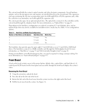
...system's control circuitry and other electronic components. Depending on the hard drive configuration you may also be required to a RAID controller card through the front bezel displays the system's status. The hard drives connect to change a jumper setting. During an installation or troubleshooting...restricts access to two full-length PCIe or PCI-X expansion cards, while the central riser accommodates one half-length PCIe expansion card. For more information, see "Hard Drives" on page 55 and "SAS Controller Daughter Card" on the system board. The optical drive connects to eight...
...system's control circuitry and other electronic components. Depending on the hard drive configuration you may also be required to a RAID controller card through the front bezel displays the system's status. The hard drives connect to change a jumper setting. During an installation or troubleshooting...restricts access to two full-length PCIe or PCI-X expansion cards, while the central riser accommodates one half-length PCIe expansion card. For more information, see "Hard Drives" on page 55 and "SAS Controller Daughter Card" on the system board. The optical drive connects to eight...
Hardware Owner's Manual (PDF)
Page 76
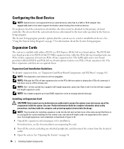
... for installation. See "Opening the System" on the central riser supports half-length expansion cards only. See support.dell.com for complete information about the System Setup program. See "Using the System Setup Program" on the PCIe left riser board option. The half-height center riser board provided with either a PCI-X or a PCI Express (PCIe...
... for installation. See "Opening the System" on the central riser supports half-length expansion cards only. See support.dell.com for complete information about the System Setup program. See "Using the System Setup Program" on the PCIe left riser board option. The half-height center riser board provided with either a PCI-X or a PCI Express (PCIe...

Hardware Owner's Manual (PDF)
Page 77
.... See the documentation that the card-edge connector aligns with the front card guide. 4 Open the expansion-card guide latch and remove the filler bracket. Installing System Components 77 See "Closing the System" on the expansion-card riser board. c Insert the card-edge connector firmly into the PCI card connector until the card is seated in the connector...
.... See the documentation that the card-edge connector aligns with the front card guide. 4 Open the expansion-card guide latch and remove the filler bracket. Installing System Components 77 See "Closing the System" on the expansion-card riser board. c Insert the card-edge connector firmly into the PCI card connector until the card is seated in the connector...

Hardware Owner's Manual (PDF)
Page 80
... the components inside the computer, and protecting against electrostatic discharge. See "Removing the Central Riser Board" on page 54. 3 Remove the plastic filler plug from the electrical outlet. 2 Open the system. Installing a RAC Card 2 3 4 1 5 6 1 RAC-card connectors (2) 4 RAC card 2 RAC-card cables (2) 5 filler plug 80 Installing System Components 3 retention standoff hole 6 support standoffs holes(2) See...
... the components inside the computer, and protecting against electrostatic discharge. See "Removing the Central Riser Board" on page 54. 3 Remove the plastic filler plug from the electrical outlet. 2 Open the system. Installing a RAC Card 2 3 4 1 5 6 1 RAC-card connectors (2) 4 RAC card 2 RAC-card cables (2) 5 filler plug 80 Installing System Components 3 retention standoff hole 6 support standoffs holes(2) See...

Hardware Owner's Manual (PDF)
Page 81
... board connector, and press down and forward on the blue tray release tab and slide the drive tray out of the card until it is fully seated. See "Installing the Central Riser Board" on page 53. 3 Open the system. See "Opening the System" on . See Figure 3-20. b Connect the second cable... to connector 2 on the RAC card and to their power sources, and turn them on page 54 4 Disconnect the optical drive cable ...
... board connector, and press down and forward on the blue tray release tab and slide the drive tray out of the card until it is fully seated. See "Installing the Central Riser Board" on page 53. 3 Open the system. See "Opening the System" on . See Figure 3-20. b Connect the second cable... to connector 2 on the RAC card and to their power sources, and turn them on page 54 4 Disconnect the optical drive cable ...

Hardware Owner's Manual (PDF)
Page 98
..., turn off the system and attached peripherals, and disconnect the system from the left riser expansion-card slots. Expansion-Card Riser Boards Removing the Left Expansion-Card Riser Board CAUTION: Only trained service technicians are authorized to confirm that the battery is operating...Opening the System" on page 78. 5 Remove the expansion-card riser board: a Pull the expansion-card riser release pin. See Figure 3-31. c Lift the riser board from the expansion card openings. See "Removing an Expansion Card" on obtaining technical assistance. See your Product Information Guide for...
..., turn off the system and attached peripherals, and disconnect the system from the left riser expansion-card slots. Expansion-Card Riser Boards Removing the Left Expansion-Card Riser Board CAUTION: Only trained service technicians are authorized to confirm that the battery is operating...Opening the System" on page 78. 5 Remove the expansion-card riser board: a Pull the expansion-card riser release pin. See Figure 3-31. c Lift the riser board from the expansion card openings. See "Removing an Expansion Card" on obtaining technical assistance. See your Product Information Guide for...

Hardware Owner's Manual (PDF)
Page 99
... components inside the computer, and protecting against electrostatic discharge. 1 Place the riser board in the expansion-card cage so that the six securing tabs are fully inserted in the expansion-card slots. See your Product Information Guide for complete information about safety precautions, working... inside the system. See "Replacing the Expansion-Card Cage" on page 79. 4 Install all expansion cards in the six securing slots on the riser board. See "Installing an Expansion Card" on page 55. See "Closing the System" on page 76. 5 ...
... components inside the computer, and protecting against electrostatic discharge. 1 Place the riser board in the expansion-card cage so that the six securing tabs are fully inserted in the expansion-card slots. See your Product Information Guide for complete information about safety precautions, working... inside the system. See "Replacing the Expansion-Card Cage" on page 79. 4 Install all expansion cards in the six securing slots on the riser board. See "Installing an Expansion Card" on page 55. See "Closing the System" on page 76. 5 ...

Hardware Owner's Manual (PDF)
Page 100
...Riser Board 2 3 1 4 5 1 card guide (2) 4 guide pins (2) 2 release tab 5 system board socket 3 central riser board Installing the Central Riser Board 1 Fitting the two guides over the guide pins on either end, and draw the riser away from the system board. Figure 3-32. See Figure 3-32. 100 Installing System Components Removing the Central Riser... discharge. 1 Press the blue release tab in the center of the central riser to remove the system cover and access any of the riser upward. 2 Lift the central riser board from the two guide pins on the system board, gently lower the ...
...Riser Board 2 3 1 4 5 1 card guide (2) 4 guide pins (2) 2 release tab 5 system board socket 3 central riser board Installing the Central Riser Board 1 Fitting the two guides over the guide pins on either end, and draw the riser away from the system board. Figure 3-32. See Figure 3-32. 100 Installing System Components Removing the Central Riser... discharge. 1 Press the blue release tab in the center of the central riser to remove the system cover and access any of the riser upward. 2 Lift the central riser board from the two guide pins on the system board, gently lower the ...


