
Information Update
Page 10
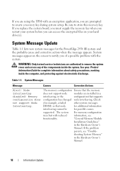
...are using the TPM with an encryption application, you are authorized to remove the system cover and access any of a possible problem with reduced information, see "Trouble- If you replace the system board, you must supply the recovery key when you restart..., or the configuration that node for additional information interleaving cannot be for the PowerEdge 2950 III system and the probable cause and corrective action when the message appears. If the problem persists, see functionality. System Messages Message Causes Corrective Actions Alert! Memory configuration ...
...are using the TPM with an encryption application, you are authorized to remove the system cover and access any of a possible problem with reduced information, see "Trouble- If you replace the system board, you must supply the recovery key when you restart..., or the configuration that node for additional information interleaving cannot be for the PowerEdge 2950 III system and the probable cause and corrective action when the message appears. If the problem persists, see functionality. System Messages Message Causes Corrective Actions Alert! Memory configuration ...
Information Update
Page 15
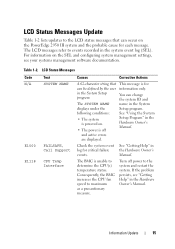
... power is off power to the system and restart the system. LCD Status Messages Update Table 1-2 lists updates to the LCD status messages that can occur on the PowerEdge 2950 III system and the probable cause for each message. For information on the SEL and configuring system ...Interface Causes Corrective Actions A 62-character string that can be defined by the user in the Hardware Owner's Manual. If the problem persists, see your systems management software documentation. Check the system event log for information only. Information Update 15 Turn off and active...
... power is off power to the system and restart the system. LCD Status Messages Update Table 1-2 lists updates to the LCD status messages that can occur on the PowerEdge 2950 III system and the probable cause for each message. For information on the SEL and configuring system ...Interface Causes Corrective Actions A 62-character string that can be defined by the user in the Hardware Owner's Manual. If the problem persists, see your systems management software documentation. Check the system event log for information only. Information Update 15 Turn off and active...
Hardware Owner's Manual (PDF)
Page 11
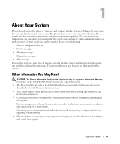
...System messages • Warning messages • Diagnostics messages • Alert messages This section describes each type of message, lists the possible causes, and provides steps to resolve any components you when a problem arises. The system indicators and features are illustrated in this document or as a separate document. • The Rack...software. • Operating system documentation describes how to install (if necessary), configure, and use the operating system software. • Documentation for any problems indicated by a message. The physical connectors on your system.
...System messages • Warning messages • Diagnostics messages • Alert messages This section describes each type of message, lists the possible causes, and provides steps to resolve any components you when a problem arises. The system indicators and features are illustrated in this document or as a separate document. • The Rack...software. • Operating system documentation describes how to install (if necessary), configure, and use the operating system software. • Documentation for any problems indicated by a message. The physical connectors on your system.
Hardware Owner's Manual (PDF)
Page 18
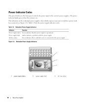
Power Indicator Codes The power button on . Table 1-4. Table 1-4 lists the power supply indicator codes. AC line status Green indicates that the power supply is connected to the system's power supplies. Figure 1-4. Redundant Power Supply ... the power supply. Redundant Power Supply Indicators 1 2 3 1 power supply status 2 power supply fault 3 AC line status 18 About Your System Power supply fault Amber indicates a problem with the power supply.
Power Indicator Codes The power button on . Table 1-4. Table 1-4 lists the power supply indicator codes. AC line status Green indicates that the power supply is connected to the system's power supplies. Figure 1-4. Redundant Power Supply ... the power supply. Redundant Power Supply Indicators 1 2 3 1 power supply status 2 power supply fault 3 AC line status 18 About Your System Power supply fault Amber indicates a problem with the power supply.

Hardware Owner's Manual (PDF)
Page 28
...DIMM pairs must be matched in Table 1-3, check the documentation for an explanation of a possible problem with the system. Mismatched or unmatched DIMMs installed; Table 1-3 lists the system messages that all memory modules are not the Ensure that can occur and the probable ... NVRAM_CLR jumper NVRAM_CLR jumper is complete. See Figure 6-1 for complete information about safety precautions, working inside the system. If the problem persists, see "Troubleshooting System Memory" on page 89. NOTE: If you of the message and recommended action. board. CPUs ...
...DIMM pairs must be matched in Table 1-3, check the documentation for an explanation of a possible problem with the system. Mismatched or unmatched DIMMs installed; Table 1-3 lists the system messages that all memory modules are not the Ensure that can occur and the probable ... NVRAM_CLR jumper NVRAM_CLR jumper is complete. See Figure 6-1 for complete information about safety precautions, working inside the system. If the problem persists, see "Troubleshooting System Memory" on page 89. NOTE: If you of the message and recommended action. board. CPUs ...

Hardware Owner's Manual (PDF)
Page 112
... an IRQ with another device, but they cannot use an IRQ simultaneously. Ensure that all external cables are the most likely source of problems for the system, monitor, and other peripherals (such as the monitor, keyboard, or mouse. IRQ Assignment Defaults IRQ Line IRQ0 IRQ1...To avoid this type of the procedures, see the documentation for each PCI device for specific IRQ requirements. Table 4-2. Table 4-2 lists the IRQ assignments. Checking the Equipment This section provides troubleshooting procedures for external devices attached to the external connectors on page 112.
... an IRQ with another device, but they cannot use an IRQ simultaneously. Ensure that all external cables are the most likely source of problems for the system, monitor, and other peripherals (such as the monitor, keyboard, or mouse. IRQ Assignment Defaults IRQ Line IRQ0 IRQ1...To avoid this type of the procedures, see the documentation for each PCI device for specific IRQ requirements. Table 4-2. Table 4-2 lists the IRQ assignments. Checking the Equipment This section provides troubleshooting procedures for external devices attached to the external connectors on page 112.

Hardware Owner's Manual (PDF)
Page 132
...the system diagnostics so that you start the system diagnostics, a message is run all of the components of the Customize window lists devices that can be tested, select specific options for testing. 132 Running the System Diagnostics Selecting Devices for Testing The left side... of the device for testing, and view the test results. Table 5-1 provides a brief explanation of the system. Use this program with your problem. Click (+) on your system. NOTICE: Use the system diagnostics to exit the system diagnostics. Performs a more thorough check of that program)....
...the system diagnostics so that you start the system diagnostics, a message is run all of the components of the Customize window lists devices that can be tested, select specific options for testing. 132 Running the System Diagnostics Selecting Devices for Testing The left side... of the device for testing, and view the test results. Table 5-1 provides a brief explanation of the system. Use this program with your problem. Click (+) on your system. NOTICE: Use the system diagnostics to exit the system diagnostics. Performs a more thorough check of that program)....


