
Information Update
Page 11
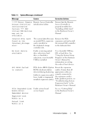
.... Invalid PCIe card found in the Hardware Owner's Manual. PCIe Degraded Link Faulty system board Width Error: or riser board. Embedded device See see "Troubleshooting System Expansion Cards" in the Hardware Owner's Manual. PCI BIOS failed to loose; See "Installing a RAC Card" in the Internal_Storage slot! Remote Access Controller initialization failure Ensure...
.... Invalid PCIe card found in the Hardware Owner's Manual. PCIe Degraded Link Faulty system board Width Error: or riser board. Embedded device See see "Troubleshooting System Expansion Cards" in the Hardware Owner's Manual. PCI BIOS failed to loose; See "Installing a RAC Card" in the Internal_Storage slot! Remote Access Controller initialization failure Ensure...
Information Update
Page 16
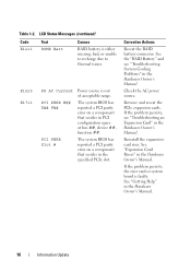
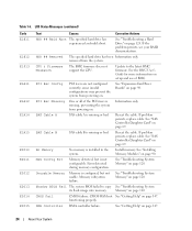
... System Cooling Problems" in the Hardware Owner's Manual. If the problem persists, the riser card or system board is out of acceptable range. E1625 E1711 PS AC Current PCI PERR B## D## F## PCI PERR Slot # Power source is faulty. Corrective Actions Reseat the RAID battery connector. ...See "Getting Help" in the Hardware Owner's Manual. See "Expansion Card Risers" in the Hardware Owner's Manual. See the ...
... System Cooling Problems" in the Hardware Owner's Manual. If the problem persists, the riser card or system board is out of acceptable range. E1625 E1711 PS AC Current PCI PERR B## D## F## PCI PERR Slot # Power source is faulty. Corrective Actions Reseat the RAID battery connector. ...See "Getting Help" in the Hardware Owner's Manual. See "Expansion Card Risers" in the Hardware Owner's Manual. See the ...
Information Update
Page 17
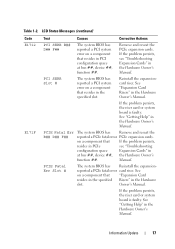
... Cards" in the specified slot. Reinstall the expansioncard riser. Manual. Table 1-2. If the problem persists, the riser card or system board is faulty. on a component that "Expansion Card resides in the specified Risers" in PCI configuration space at bus ##, device ##, the Hardware ...Owner's function ##. See "Expansion Card Risers" in the Hardware Owner's Manual. PCIE Fatal Err B## D## F## The system BIOS...
... Cards" in the specified slot. Reinstall the expansioncard riser. Manual. Table 1-2. If the problem persists, the riser card or system board is faulty. on a component that "Expansion Card resides in the specified Risers" in PCI configuration space at bus ##, device ##, the Hardware ...Owner's function ##. See "Expansion Card Risers" in the Hardware Owner's Manual. PCIE Fatal Err B## D## F## The system BIOS...
Getting Started Guide
Page 6
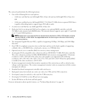
See support.dell.com for the latest support information about specific features, see "Technical Specifications" on separate PCI-X buses (capable of throttling back to support legacy PCI add-in cards). • A center riser card that has one half-length PCIe x8 lane slot. • Dedicated slot for remote systems...management. • An integrated VGA-compatible video subsystem with 256 MB of cache memory and a RAID battery. A left riser card that has two full-length PCI-X 3.3-V, 64-bit,133-MHz slots on page 10. 4 Getting Started With Your System NOTE: System boot is not supported...
See support.dell.com for the latest support information about specific features, see "Technical Specifications" on separate PCI-X buses (capable of throttling back to support legacy PCI add-in cards). • A center riser card that has one half-length PCIe x8 lane slot. • Dedicated slot for remote systems...management. • An integrated VGA-compatible video subsystem with 256 MB of cache memory and a RAID battery. A left riser card that has two full-length PCI-X 3.3-V, 64-bit,133-MHz slots on page 10. 4 Getting Started With Your System NOTE: System boot is not supported...

Getting Started Guide
Page 12
PCI-X, PCIe one half-height x8 lane 3.3-V (slot 1) two full-height, full-length 3.3-V, 64-bit, 133-MHz (slots 2 and 3) OR one full-height x8 lane 3.3-V (slot 2) ... drives one optional 3.5-inch, 1.44-MB external optional USB 3.5-inch, 1.44-MB Technical Specifications Processor Processor type Expansion Bus Bus type Expansion slots Center riser: PCIe Left riser PCI-X option: PCIe option: Memory Architecture Memory module sockets Memory module capacities Minimum RAM Maximum RAM Drives Hard drives Diskette drive 10 Getting Started With...
PCI-X, PCIe one half-height x8 lane 3.3-V (slot 1) two full-height, full-length 3.3-V, 64-bit, 133-MHz (slots 2 and 3) OR one full-height x8 lane 3.3-V (slot 2) ... drives one optional 3.5-inch, 1.44-MB external optional USB 3.5-inch, 1.44-MB Technical Specifications Processor Processor type Expansion Bus Bus type Expansion slots Center riser: PCIe Left riser PCI-X option: PCIe option: Memory Architecture Memory module sockets Memory module capacities Minimum RAM Maximum RAM Drives Hard drives Diskette drive 10 Getting Started With...

Hardware Owner's Manual (PDF)
Page 8
... System Board Jumpers 135 System Board Connectors 137 SAS Backplane Board Connectors 139 Sideplane Board Connectors 142 Expansion-Card Riser-Board Components and PCI Buses 142 Disabling a Forgotten Password 144 7 Getting Help 147 Technical Assistance 147 Online Services 147 AutoTech Service ...148 Automated Order-Status Service 148 Technical Support Service 148 Dell Enterprise Training and Certification 149 Problems With Your Order ...
... System Board Jumpers 135 System Board Connectors 137 SAS Backplane Board Connectors 139 Sideplane Board Connectors 142 Expansion-Card Riser-Board Components and PCI Buses 142 Disabling a Forgotten Password 144 7 Getting Help 147 Technical Assistance 147 Online Services 147 AutoTech Service ...148 Automated Order-Status Service 148 Technical Support Service 148 Dell Enterprise Training and Certification 149 Problems With Your Order ...

Hardware Owner's Manual (PDF)
Page 17
Back-Panel Features and Indicators 1 2 3 4 13 12 11 10 9 87 6 5 1 center PCI riser (slot 1) 4 power supplies (2) 7 system status indicator connector 10 USB connectors (2) 13 remote access controller (optional) 2 left PCI riser (slot 2) 5 system identification button 8 NIC2 connector 3 left PCI riser (slot 3) 6 system status indicator 9 NIC1 connector 11 video connector 12 serial connector Connecting External Devices When connecting...
Back-Panel Features and Indicators 1 2 3 4 13 12 11 10 9 87 6 5 1 center PCI riser (slot 1) 4 power supplies (2) 7 system status indicator connector 10 USB connectors (2) 13 remote access controller (optional) 2 left PCI riser (slot 2) 5 system identification button 8 NIC2 connector 3 left PCI riser (slot 3) 6 system status indicator 9 NIC1 connector 11 video connector 12 serial connector Connecting External Devices When connecting...

Hardware Owner's Manual (PDF)
Page 23
... error on page 147. E1810 HDD ## Fault The SAS subsystem has determined that resides in PCI configuration space at bus ##, device ##, function ##. See "Expansion-Card Cage" on page 147. If the problem persists, the riser card or system board is faulty. See "Getting Help" on page 78. If the problem persists, see...
... error on page 147. E1810 HDD ## Fault The SAS subsystem has determined that resides in PCI configuration space at bus ##, device ##, function ##. See "Expansion-Card Cage" on page 147. If the problem persists, the riser card or system board is faulty. See "Getting Help" on page 78. If the problem persists, see...
Hardware Owner's Manual (PDF)
Page 24
If the problem persists, see your RAID documentation. PCI Rsr Config PCI risers are not configured correctly; See "Expansion-Card Riser Boards" on page 124. Reseat the cable. No Memory No memory is missing, preventing the system from powering on. CMOS Fail ...If problem persists, replace cable. If problem persists, replace cable. Memory subsystem failure. See "Troubleshooting System Memory" on setup and use of the PCI risers is installed in the system. CMOS RAM not See "Getting Help" on page 90. HDD ## Removed The specified hard drive has been Information ...
If the problem persists, see your RAID documentation. PCI Rsr Config PCI risers are not configured correctly; See "Expansion-Card Riser Boards" on page 124. Reseat the cable. No Memory No memory is missing, preventing the system from powering on. CMOS Fail ...If problem persists, replace cable. If problem persists, replace cable. Memory subsystem failure. See "Troubleshooting System Memory" on setup and use of the PCI risers is installed in the system. CMOS RAM not See "Getting Help" on page 90. HDD ## Removed The specified hard drive has been Information ...
Hardware Owner's Manual (PDF)
Page 53
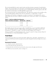
... Bezel 1 Using the system key, unlock the bezel. 2 Press the tab at the left end of the bezel. 3 Rotate the left riser accommodates up to change a jumper setting. Several hardware options, such as the microprocessors and memory, are installed directly on the system board through the...configuration options. See Table 3-1 for an optional optical drive. The hard drives connect to two full-length PCIe or PCI-X expansion cards, while the central riser accommodates one half-length PCIe expansion card. Installing System Components 53 The expansioncard cage containing the left end of the ...
... Bezel 1 Using the system key, unlock the bezel. 2 Press the tab at the left end of the bezel. 3 Rotate the left riser accommodates up to change a jumper setting. Several hardware options, such as the microprocessors and memory, are installed directly on the system board through the...configuration options. See Table 3-1 for an optional optical drive. The hard drives connect to two full-length PCIe or PCI-X expansion cards, while the central riser accommodates one half-length PCIe expansion card. Installing System Components 53 The expansioncard cage containing the left end of the ...
Hardware Owner's Manual (PDF)
Page 76
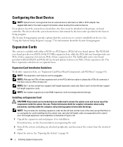
...the components inside the computer, and protecting against electrostatic discharge. For instructions, see "Expansion-Card Riser-Board Components and PCI Buses" on the central riser. See support.dell.com for complete information about the System Setup program. Installing an Expansion Card CAUTION: Only trained...up to two RAID expansion cards to the primary (or boot) controller. The half-height center riser board provided with either a PCI-X or a PCI Express (PCIe) left riser board provides one PCIe x8-lane expansion slot and one PCIe x8-lane expansion slot. See "Opening...
...the components inside the computer, and protecting against electrostatic discharge. For instructions, see "Expansion-Card Riser-Board Components and PCI Buses" on the central riser. See support.dell.com for complete information about the System Setup program. Installing an Expansion Card CAUTION: Only trained...up to two RAID expansion cards to the primary (or boot) controller. The half-height center riser board provided with either a PCI-X or a PCI Express (PCIe) left riser board provides one PCIe x8-lane expansion slot and one PCIe x8-lane expansion slot. See "Opening...

Hardware Owner's Manual (PDF)
Page 77
...Position the expansion card so that came with the expansion-card connector on page 55. c Insert the card-edge connector firmly into the PCI card connector until the card is seated in the connector, close the expansion-card latch. See the documentation that the card-edge connector aligns... Components 77 4 Open the expansion-card guide latch and remove the filler bracket. See Figure 3-18. See "Closing the System" on the expansion-card riser board. See Figure 3-18. 5 Install the expansion card: a If the expansion card is full length, align its cable connections. 7 Close the system...
...Position the expansion card so that came with the expansion-card connector on page 55. c Insert the card-edge connector firmly into the PCI card connector until the card is seated in the connector, close the expansion-card latch. See the documentation that the card-edge connector aligns... Components 77 4 Open the expansion-card guide latch and remove the filler bracket. See Figure 3-18. See "Closing the System" on the expansion-card riser board. See Figure 3-18. 5 Install the expansion card: a If the expansion card is full length, align its cable connections. 7 Close the system...

Hardware Owner's Manual (PDF)
Page 142
Figure 6-6. Sideplane Board Connectors 1 2 3 4 5 6 1 control panel (CTRL) 4 CD IDE (IDE) 2 SAS controller daughter card 3 chassis intrusion switch (PCIE_STORAGE) 5 pin guides (2) 6 system board connector Expansion-Card Riser-Board Components and PCI Buses Figure 6-7, Figure 6-8, and Figure 6-9 show the components on the sideplane board. Sideplane Board Connectors See Figure 6-6 for the location and description of connectors on the optional PCI-X/PCIe expansion-card riser boards, including the expansion-card slots and buses. 142 Jumpers and Connectors
Figure 6-6. Sideplane Board Connectors 1 2 3 4 5 6 1 control panel (CTRL) 4 CD IDE (IDE) 2 SAS controller daughter card 3 chassis intrusion switch (PCIE_STORAGE) 5 pin guides (2) 6 system board connector Expansion-Card Riser-Board Components and PCI Buses Figure 6-7, Figure 6-8, and Figure 6-9 show the components on the sideplane board. Sideplane Board Connectors See Figure 6-6 for the location and description of connectors on the optional PCI-X/PCIe expansion-card riser boards, including the expansion-card slots and buses. 142 Jumpers and Connectors

Hardware Owner's Manual (PDF)
Page 143
Figure 6-7. Optional PCI-X Left Expansion-Card Riser Board Components 1 2 3 slot 3 PCIe x4 lane width 3 1 riser release pin 4 pin guide (2) 5 2 slot 2 PCI-X 133-MHz 5 system board connector 4 3 slot 3 PCI-X 133-MHz Jumpers and Connectors 143 Optional PCIe Left Expansion-Card Riser Board Components 1 2 3 4 5 1 riser release pin 4 pin guide (2) 2 slot 2 PCIe x8 lane width 5 system board connector Figure 6-8.
Figure 6-7. Optional PCI-X Left Expansion-Card Riser Board Components 1 2 3 slot 3 PCIe x4 lane width 3 1 riser release pin 4 pin guide (2) 5 2 slot 2 PCI-X 133-MHz 5 system board connector 4 3 slot 3 PCI-X 133-MHz Jumpers and Connectors 143 Optional PCIe Left Expansion-Card Riser Board Components 1 2 3 4 5 1 riser release pin 4 pin guide (2) 2 slot 2 PCIe x8 lane width 5 system board connector Figure 6-8.

Hardware Owner's Manual (PDF)
Page 144
Optional PCIe Expansion-Card Central Riser Board Components 1 2 1 slot 1 PCI-X - NOTE: If you must install the jumper plug. Figure 6-9. NOTICE: See "Protecting Against Electrostatic Discharge" in the safety instructions in use. The existing passwords are ...
Optional PCIe Expansion-Card Central Riser Board Components 1 2 1 slot 1 PCI-X - NOTE: If you must install the jumper plug. Figure 6-9. NOTICE: See "Protecting Against Electrostatic Discharge" in the safety instructions in use. The existing passwords are ...

Hardware Owner's Manual (PDF)
Page 178
..., 142 expansion-card cage removing, 78 replacing, 79 expansion-card riser board connectors, 142 PCI buses, 142 external devices connecting, 17 F fan bracket removing, 68 replacing, 69 features back-panel, 17 front-panel, 13 G guidelines expansion card installation, 76 guidelines ..., 106 diskette drive, 84 diskette drive into drive carrier, 85 expansion card, 76 expansion card guidelines, 76 hard drive blank, 57 hard drives, 57 left riser board, 98 memory, 90 memory guidelines, 89 optical drive, 82 power supply blank, 65 processor, 93, 95 RAID battery, 74 installing (continued) SAS backplane ...
..., 142 expansion-card cage removing, 78 replacing, 79 expansion-card riser board connectors, 142 PCI buses, 142 external devices connecting, 17 F fan bracket removing, 68 replacing, 69 features back-panel, 17 front-panel, 13 G guidelines expansion card installation, 76 guidelines ..., 106 diskette drive, 84 diskette drive into drive carrier, 85 expansion card, 76 expansion card guidelines, 76 hard drive blank, 57 hard drives, 57 left riser board, 98 memory, 90 memory guidelines, 89 optical drive, 82 power supply blank, 65 processor, 93, 95 RAID battery, 74 installing (continued) SAS backplane ...
Hardware Owner's Manual (PDF)
Page 179
... 82 removing, 81 options system setup, 38 P password disabling, 144 password features setup, 45 system, 45 passwords setup, 47 system, 45 PCI buses expansion-card riser board, 142 POST accessing system features, 12 power indicator, 18 power supplies removing, 63 replacing, 64 troubleshooting, 118 power supply blank, 64 ..., 78 expansion-card cage, 78 fan bracket, 68 hard drive blank, 56 hard drive from a drive carrier, 58 hard drives, 57 left riser, 99 left riser board, 98 memory, 92 optical drive, 81 power supply, 63 power supply blank, 64 processor, 93, 95 RAID battery, 75 SAS backplane ...
... 82 removing, 81 options system setup, 38 P password disabling, 144 password features setup, 45 system, 45 passwords setup, 47 system, 45 PCI buses expansion-card riser board, 142 POST accessing system features, 12 power indicator, 18 power supplies removing, 63 replacing, 64 troubleshooting, 118 power supply blank, 64 ..., 78 expansion-card cage, 78 fan bracket, 68 hard drive blank, 56 hard drive from a drive carrier, 58 hard drives, 57 left riser, 99 left riser board, 98 memory, 92 optical drive, 81 power supply, 63 power supply blank, 64 processor, 93, 95 RAID battery, 75 SAS backplane ...


