
Hardware Owner's Manual (PDF)
Page 25
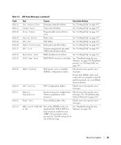
... your DRAC documentation. POST Fail General failure after video. SMI Init System management interrupt See "Getting Help" on page 147. Check screen for specific error messages. See ..."Troubleshooting System Memory" on page 147. Ensure that DRAC cables and connectors are properly seated. CPU Config CPU configuration failure. Check screen for specific... "Getting Help" on page 147. See "Getting Help" on page 147. DRAC Config Dell remote access controller Check screen for specific error Memory population order messages. Table 1-6. If no...
... your DRAC documentation. POST Fail General failure after video. SMI Init System management interrupt See "Getting Help" on page 147. Check screen for specific error messages. See ..."Troubleshooting System Memory" on page 147. Ensure that DRAC cables and connectors are properly seated. CPU Config CPU configuration failure. Check screen for specific... "Getting Help" on page 147. See "Getting Help" on page 147. DRAC Config Dell remote access controller Check screen for specific error Memory population order messages. Table 1-6. If no...
Hardware Owner's Manual (PDF)
Page 63
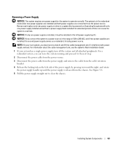
... has a single power supply, turn off the system and all attached peripherals. Operating the system with power supply removal. For information about the cable management arm, see the system's Rack Installation Guide. 1 If your rack system, you can cause the system to overheat. Installing System Components 63 ...and if two power supplies are connected to an AC power source. For a redundant system, you may have to unlatch and lift the cable management arm if it must be installed in a system that is installed, it interferes with only one power supply for extended periods of time ...
... has a single power supply, turn off the system and all attached peripherals. Operating the system with power supply removal. For information about the cable management arm, see the system's Rack Installation Guide. 1 If your rack system, you can cause the system to overheat. Installing System Components 63 ...and if two power supplies are connected to an AC power source. For a redundant system, you may have to unlatch and lift the cable management arm if it must be installed in a system that is installed, it interferes with only one power supply for extended periods of time ...

Hardware Owner's Manual (PDF)
Page 80
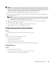
...Remove the plastic filler plug from the electrical outlet. 2 Open the system. Figure 3-20. See your Product Information Guide for managing the server remotely. The following procedure describes the steps for installing the optional RAC card. 1 Turn off the system, including ... safety precautions, working inside the system. Installing a RAC Card 2 3 4 1 5 6 1 RAC-card connectors (2) 4 RAC card 2 RAC-card cables (2) 5 filler plug 80 Installing System Components 3 retention standoff hole 6 support standoffs holes(2) The optional Remote Access Controller (RAC) provides a set of the...
...Remove the plastic filler plug from the electrical outlet. 2 Open the system. Figure 3-20. See your Product Information Guide for managing the server remotely. The following procedure describes the steps for installing the optional RAC card. 1 Turn off the system, including ... safety precautions, working inside the system. Installing a RAC Card 2 3 4 1 5 6 1 RAC-card connectors (2) 4 RAC card 2 RAC-card cables (2) 5 filler plug 80 Installing System Components 3 retention standoff hole 6 support standoffs holes(2) The optional Remote Access Controller (RAC) provides a set of the...

Hardware Owner's Manual (PDF)
Page 112
.... See "Front-Panel Features and Indicators" on page 13 and "Back-Panel Features and Indicators" on page 17 for power management) Available Available PS/2 mouse port unless the mouse is disabled through the System Setup program Math coprocessor IDE CD drive controller Available... Troubleshooting External Connections Loose or improperly connected cables are securely attached to the system, such as a printer, keyboard, mouse, or other peripherals (such as the monitor, keyboard,...
.... See "Front-Panel Features and Indicators" on page 13 and "Back-Panel Features and Indicators" on page 17 for power management) Available Available PS/2 mouse port unless the mouse is disabled through the System Setup program Math coprocessor IDE CD drive controller Available... Troubleshooting External Connections Loose or improperly connected cables are securely attached to the system, such as a printer, keyboard, mouse, or other peripherals (such as the monitor, keyboard,...
Hardware Owner's Manual (PDF)
Page 119
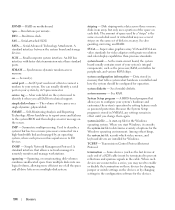
...; System-status indicator is working properly. Operating the system for the system to operate. Troubleshooting System Cooling Problems Problem • Systems management software issues a fan-related error message. Remove and install only one power supply installed, without a power supply blank installed, can...5 Install a new power supply. Action Ensure that is powered on page 63. 3 Ensure that the power supply is obstructed. • Cables inside the system obstruct airflow. • An individual cooling fan has failed. See "Removing a Power Supply" on page 64. NOTICE: You...
...; System-status indicator is working properly. Operating the system for the system to operate. Troubleshooting System Cooling Problems Problem • Systems management software issues a fan-related error message. Remove and install only one power supply installed, without a power supply blank installed, can...5 Install a new power supply. Action Ensure that is powered on page 63. 3 Ensure that the power supply is obstructed. • Cables inside the system obstruct airflow. • An individual cooling fan has failed. See "Removing a Power Supply" on page 64. NOTICE: You...
Hardware Owner's Manual (PDF)
Page 174
... devices. Second(s). An I/O port used . A bar code label on the devices or by changing settings in the cable. SMART - Symmetric multiprocessing. Simple Network Management Protocol. Spanning, or concatenating, disk volumes combines unallocated space from multiple disks into one logical volume, allowing more efficient ... the same set of space used to identify it consults the system.ini file to remotely monitor and manage workstations. SVGA - Data stored in a series, you call Dell for the Windows operating environment. See RAM. system.ini file - Among other things, the system.ini...
... devices. Second(s). An I/O port used . A bar code label on the devices or by changing settings in the cable. SMART - Symmetric multiprocessing. Simple Network Management Protocol. Spanning, or concatenating, disk volumes combines unallocated space from multiple disks into one logical volume, allowing more efficient ... the same set of space used to identify it consults the system.ini file to remotely monitor and manage workstations. SVGA - Data stored in a series, you call Dell for the Windows operating environment. See RAM. system.ini file - Among other things, the system.ini...
Hardware Owner's Manual (PDF)
Page 175
...to be integrated into the system board or may need to determine a variety of use, enhanced workgroup functionality, and simplified file management and browsing. Windows Powered - Universal Internet Exchange. Uninterruptible power supply. Unshielded twisted pair. video resolution - Watt(s). A start ...require MS-DOS and that allows graphics-mode application programs and operating systems to other hubs or switches without requiring a crossover cable. memory, disk drives, or printers, for example) is a way to create common information formats and to share both...
...to be integrated into the system board or may need to determine a variety of use, enhanced workgroup functionality, and simplified file management and browsing. Windows Powered - Universal Internet Exchange. Uninterruptible power supply. Unshielded twisted pair. video resolution - Watt(s). A start ...require MS-DOS and that allows graphics-mode application programs and operating systems to other hubs or switches without requiring a crossover cable. memory, disk drives, or printers, for example) is a way to create common information formats and to share both...
Rack Installation Guide
Page 5
... Mounting Rails 12 Installing the VersaRails Mounting Rails 13 Installing the System in the Rack 15 Removing the System From the Rack 16 Installing the Cable-Management Arm 17 Routing Cables 18 Attaching the Cable-Management Arm Ramp Assembly 19 Replacing the Rack Doors 21 Contents 3
... Mounting Rails 12 Installing the VersaRails Mounting Rails 13 Installing the System in the Rack 15 Removing the System From the Rack 16 Installing the Cable-Management Arm 17 Routing Cables 18 Attaching the Cable-Management Arm Ramp Assembly 19 Replacing the Rack Doors 21 Contents 3

Rack Installation Guide
Page 9
...use in marking the mounting holes to be used Rack Kit Contents • One pair of slide assemblies • One cable-management arm • One left cable-management arm ramp assemblies are identified by size and number of threads per inch is identified as a 10-32 screw. Recommended ...with the rack cabinet for use one ramp assembly to secure the CMA to tip over . For more information, see "Attaching the Cable-Management Arm Ramp Assembly" on installing and anchoring the stabilizer feet. Failure to install stabilizers accordingly before installing components in a rack could ...
...use in marking the mounting holes to be used Rack Kit Contents • One pair of slide assemblies • One cable-management arm • One left cable-management arm ramp assemblies are identified by size and number of threads per inch is identified as a 10-32 screw. Recommended ...with the rack cabinet for use one ramp assembly to secure the CMA to tip over . For more information, see "Attaching the Cable-Management Arm Ramp Assembly" on installing and anchoring the stabilizer feet. Failure to install stabilizers accordingly before installing components in a rack could ...
Rack Installation Guide
Page 10
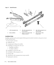
Rack Kit Contents 1 3 2 4 6 5 1 cable-management arm 4 slide assemblies 2 left cable-management arm ramp assembly 5 10-32 x 0.5-inch flange-head Phillips screws (8) 3 right cable-management arm ramp assembly 6 status indicator cable (if applicable) Installation Tasks Installing a rack kit involves performing the following tasks (... installation • VersaRails installation 5 Installing the system in the rack 6 Installing the cable-management arm 7 Routing cables 8 Attaching the cable-management arm ramp assembly 9 Replacing the rack doors 8 Rack Installation Guide Figure 1-1.
Rack Kit Contents 1 3 2 4 6 5 1 cable-management arm 4 slide assemblies 2 left cable-management arm ramp assembly 5 10-32 x 0.5-inch flange-head Phillips screws (8) 3 right cable-management arm ramp assembly 6 status indicator cable (if applicable) Installation Tasks Installing a rack kit involves performing the following tasks (... installation • VersaRails installation 5 Installing the system in the rack 6 Installing the cable-management arm 7 Routing cables 8 Attaching the cable-management arm ramp assembly 9 Replacing the rack doors 8 Rack Installation Guide Figure 1-1.
Rack Installation Guide
Page 17
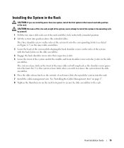
The system release latch at the front of each inner slide, then push the system into the rack. 7 Install the cable-management arm. See "Installing the Cable-Management Arm" on page 17. 8 Tighten the thumbscrews on the rack front panel to secure the slide assemblies to install the system in the mounting rails ...
The system release latch at the front of each inner slide, then push the system into the rack. 7 Install the cable-management arm. See "Installing the Cable-Management Arm" on page 17. 8 Tighten the thumbscrews on the rack front panel to secure the slide assemblies to install the system in the mounting rails ...

Rack Installation Guide
Page 19
... Both ends of the slide assembly until the latch clicks (see Figure 1-8). 2 Fit the latch on the unattached end of the cable-management arm onto the bracket on the end of the mounting rail until it stops because of the safety catch. 5 Pull up on the...system forward. 6 Pull the system completely out of system 1 mounting rails (2) 3 latches (2) 4 2 brackets (2) 4 cable-management arm Rack Installation Guide 17 Installing the Cable-Management Arm NOTE: You can attach the cable-management arm to the side opposite of where you attach the cablemanagement arm. 1 Fit the latch on the front end...
... Both ends of the slide assembly until the latch clicks (see Figure 1-8). 2 Fit the latch on the unattached end of the cable-management arm onto the bracket on the end of the mounting rail until it stops because of the safety catch. 5 Pull up on the...system forward. 6 Pull the system completely out of system 1 mounting rails (2) 3 latches (2) 4 2 brackets (2) 4 cable-management arm Rack Installation Guide 17 Installing the Cable-Management Arm NOTE: You can attach the cable-management arm to the side opposite of where you attach the cablemanagement arm. 1 Fit the latch on the front end...

Rack Installation Guide
Page 20
... cable connections, see Figure 1-9). Routing Cables on the Cable-Management Arm 1 2 1 tie wraps (2) 3 cable-management arm 4 3 2 system status-indicator cable connector 4 wire cable basket 2 If applicable, connect the system status-indicator cable to its connector on the back of the power supplies to provide strain relief for the power cables. 4 Route the cables along the bend in the cable-management arm. 5 Adjust the cable...
... cable connections, see Figure 1-9). Routing Cables on the Cable-Management Arm 1 2 1 tie wraps (2) 3 cable-management arm 4 3 2 system status-indicator cable connector 4 wire cable basket 2 If applicable, connect the system status-indicator cable to its connector on the back of the power supplies to provide strain relief for the power cables. 4 Route the cables along the bend in the cable-management arm. 5 Adjust the cable...

Rack Installation Guide
Page 21
...right cablemanagement arm ramp assembly to prevent long-term sagging of the cable-management arm. CAUTION: The cable-management arm ramp assembly must be installed to the rack (see Figure 1-10). a If the cable-management arm is attached on the side of each slide and then slide ..., level position. NOTE: The orientation shown in Figure 1-11), attach the left cable-management arm ramp assembly 2 right cable-management arm ramp assembly 3 metal ramp Rack Installation Guide 19 To attach the cable-management arm ramp assembly: 1 Select only one ramp assembly, depending on the right side...
...right cablemanagement arm ramp assembly to prevent long-term sagging of the cable-management arm. CAUTION: The cable-management arm ramp assembly must be installed to the rack (see Figure 1-10). a If the cable-management arm is attached on the side of each slide and then slide ..., level position. NOTE: The orientation shown in Figure 1-11), attach the left cable-management arm ramp assembly 2 right cable-management arm ramp assembly 3 metal ramp Rack Installation Guide 19 To attach the cable-management arm ramp assembly: 1 Select only one ramp assembly, depending on the right side...

Rack Installation Guide
Page 22
... if you have selected the correct ramp assembly, the wireform guide will seat correctly in the rack. To disengage the cable-management arm ramp assembly, press the ramp assembly release button on the right. c If you attach the cablemanagement arm on the...time the system is attached to the right side of the cable-management arm. Figure 1-11. 1 Installing the Cable-Management Arm Ramp Assembly 3 2 4 5 6 1 ramp assembly bracket 4 ramp assembly seating catch 2 cable-management arm ramp assembly latch 5 left cable-management arm ramp assembly 3 ramp assembly release button 6 ramp ...
... if you have selected the correct ramp assembly, the wireform guide will seat correctly in the rack. To disengage the cable-management arm ramp assembly, press the ramp assembly release button on the right. c If you attach the cablemanagement arm on the...time the system is attached to the right side of the cable-management arm. Figure 1-11. 1 Installing the Cable-Management Arm Ramp Assembly 3 2 4 5 6 1 ramp assembly bracket 4 ramp assembly seating catch 2 cable-management arm ramp assembly latch 5 left cable-management arm ramp assembly 3 ramp assembly release button 6 ramp ...


