Processor Upgrade Installation Guide
Page 5
... (if applicable) • Thermal grease Your upgrade kit may also include a cooling fan. See www.dell.com and support.dell.com for information on processor availability and upgrade options for your Installation and Troubleshooting Guide for the primary processor on the system board, other ZIF sockets might adhere to cool before handling. NOTICE: If...
... (if applicable) • Thermal grease Your upgrade kit may also include a cooling fan. See www.dell.com and support.dell.com for information on processor availability and upgrade options for your Installation and Troubleshooting Guide for the primary processor on the system board, other ZIF sockets might adhere to cool before handling. NOTICE: If...
Processor Upgrade Installation Guide
Page 6
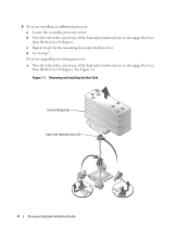
... Installation Guide See Figure 1-1. d Go to disengage the lever, then lift the lever 90 degrees. If you are upgrading an existing processor: a Press the tab on the end of one of the heat-sink retention levers to disengage the lever, then lift the lever 90 degrees. c Repeat ...-sink retention lever. b Press the tab on the end of one of the heat-sink retention levers to step 7. 6 If you are installing an additional processor: a Locate the secondary...
... Installation Guide See Figure 1-1. d Go to disengage the lever, then lift the lever 90 degrees. If you are upgrading an existing processor: a Press the tab on the end of one of the heat-sink retention levers to disengage the lever, then lift the lever 90 degrees. c Repeat ...-sink retention lever. b Press the tab on the end of one of the heat-sink retention levers to step 7. 6 If you are installing an additional processor: a Locate the secondary...
Processor Upgrade Installation Guide
Page 7
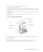
... the socket-release lever straight up so that the socket is released from the processor. Removing and Installing the Processor pin-1 corner of processor processor pin-1 corner of socket ZIF socket socket-release lever g Lift the processor out of the pins on the microprocessor appear bent, see "Getting Help" in a clockwise, then counterclockwise, direction until...
... the socket-release lever straight up so that the socket is released from the processor. Removing and Installing the Processor pin-1 corner of processor processor pin-1 corner of socket ZIF socket socket-release lever g Lift the processor out of the pins on the microprocessor appear bent, see "Getting Help" in a clockwise, then counterclockwise, direction until...
Processor Upgrade Installation Guide
Page 8
... socket. See Figure 1-1. e Repeat for the other heat-sink retention lever. 6 Processor Upgrade Installation Guide a If you are upgrading an existing processor, use force, which could bend the pins if the processor is critical to bend the pins. NOTE: Identifying the pin-1 corners is misaligned. ... one of the two heat-sink retention levers until it locks. See Figure 1-1. Identify the pin-1 corner of the processor by a corresponding triangle. 9 Install the processor in the same corner of the ZIF socket identified by locating the tiny gold triangle on . See Figure 1-2. c ...
... socket. See Figure 1-1. e Repeat for the other heat-sink retention lever. 6 Processor Upgrade Installation Guide a If you are upgrading an existing processor, use force, which could bend the pins if the processor is critical to bend the pins. NOTE: Identifying the pin-1 corners is misaligned. ... one of the two heat-sink retention levers until it locks. See Figure 1-1. Identify the pin-1 corner of the processor by a corresponding triangle. 9 Install the processor in the same corner of the ZIF socket identified by locating the tiny gold triangle on . See Figure 1-2. c ...
Processor Upgrade Installation Guide
Page 9
... 14 Close the system. 15 Reconnect your User's Guide for instructions about running the diagnostics and troubleshooting processor problems. 18 Replace the bezel (if applicable). Processor Upgrade Installation Guide 7 11 Reinstall the center fan bracket or replace the memory module shroud (if applicable...). 12 If you have added an additional processor, install the processor cooling fan(s) for information about using the System Setup program. 17 Run the system diagnostics to verify that the processor information matches the new system configuration. See "Running the System...
... 14 Close the system. 15 Reconnect your User's Guide for instructions about running the diagnostics and troubleshooting processor problems. 18 Replace the bezel (if applicable). Processor Upgrade Installation Guide 7 11 Reinstall the center fan bracket or replace the memory module shroud (if applicable...). 12 If you have added an additional processor, install the processor cooling fan(s) for information about using the System Setup program. 17 Run the system diagnostics to verify that the processor information matches the new system configuration. See "Running the System...

Processor Upgrade Installation Guide
Page 10
8 Processor Upgrade Installation Guide
8 Processor Upgrade Installation Guide
Updating Your NIC Teaming Drivers (.pdf)
Page 4
... proper installation. 10 If applicable, remove the RAC card. See "Power Supplies" in "Installing System Options" in your Installation and Troubleshooting Guide. 13 Remove the processor(s). See "Processor" in "Installing System Options" in your Installation and Troubleshooting Guide. 4 Upgrading Your System Board and Riser Board See "System Memory" in "Installing System Options...
... proper installation. 10 If applicable, remove the RAC card. See "Power Supplies" in "Installing System Options" in your Installation and Troubleshooting Guide. 13 Remove the processor(s). See "Processor" in "Installing System Options" in your Installation and Troubleshooting Guide. 4 Upgrading Your System Board and Riser Board See "System Memory" in "Installing System Options...
Updating Your NIC Teaming Drivers (.pdf)
Page 6
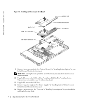
... connector on the underside of the riser board with the system board, carefully close the cam lever to a vertical position. See Figure 1-1. www.dell.com | support.dell.com 5 Replace the processor(s). 6 If applicable, replace the RAC card. 7 If applicable, replace the RAID key. 8 Replace the power supply(s). 9 Install the new riser board provided...
... connector on the underside of the riser board with the system board, carefully close the cam lever to a vertical position. See Figure 1-1. www.dell.com | support.dell.com 5 Replace the processor(s). 6 If applicable, replace the RAC card. 7 If applicable, replace the RAID key. 8 Replace the power supply(s). 9 Install the new riser board provided...
Updating Your NIC Teaming Drivers (.pdf)
Page 7
...13 If applicable, remove the RAID key. 14 Remove the power supply(s). Removing and Replacing the System Board and Riser Board In A Dell PowerEdge 2850 System Removing the System Board 1 If applicable, remove the bezel. 2 Turn off the system and attached peripherals, and disconnect the system ... from the system board. See "Power Supplies" in "Installing System Options" in your Installation and Troubleshooting Guide. 15 Remove the processor(s). See "Processor" in "Installing System Options" in your Installation and Troubleshooting Guide. 16 Raise the drive-bay retraction bar and swing it on...
...13 If applicable, remove the RAID key. 14 Remove the power supply(s). Removing and Replacing the System Board and Riser Board In A Dell PowerEdge 2850 System Removing the System Board 1 If applicable, remove the bezel. 2 Turn off the system and attached peripherals, and disconnect the system ... from the system board. See "Power Supplies" in "Installing System Options" in your Installation and Troubleshooting Guide. 15 Remove the processor(s). See "Processor" in "Installing System Options" in your Installation and Troubleshooting Guide. 16 Raise the drive-bay retraction bar and swing it on...
Updating Your NIC Teaming Drivers (.pdf)
Page 9
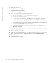
See Figure 1-3. 7 Replace the memory modules. 8 Replace the memory module cover. 9 Replace the processor(s). 10 If applicable, replace the RAC card. 11 If applicable, replace the RAID key. 12 Replace the back-fan tray and the back fans. 13 ... Troubleshooting Guide. 16 If applicable, reconnect the RAID battery cable to the left until it is completely flush with the new riser board. Upgrading the Dell PowerEdge 2850 Expansion-Card Riser Board 1 If applicable, remove the RAID memory module from the expansion-card riser board. 2 Press both release tabs on the chassis fit...
See Figure 1-3. 7 Replace the memory modules. 8 Replace the memory module cover. 9 Replace the processor(s). 10 If applicable, replace the RAC card. 11 If applicable, replace the RAID key. 12 Replace the back-fan tray and the back fans. 13 ... Troubleshooting Guide. 16 If applicable, reconnect the RAID battery cable to the left until it is completely flush with the new riser board. Upgrading the Dell PowerEdge 2850 Expansion-Card Riser Board 1 If applicable, remove the RAID memory module from the expansion-card riser board. 2 Press both release tabs on the chassis fit...


