Upgrade the BIOS Before Upgrading Your System (.pdf)
Page 1
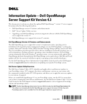
On PowerEdge systems running the latest drivers and firmware. SUU compares the drivers and firmware versions on your system with the components installed on updating your specific PowerEdge system. This utility is not included with the Dell OpenManage server support kit version 4.3 that your system is available from the Dell Support website at support.dell.com for a list of supported PowerEdge systems and operating systems. NOTE: The Dell OpenManage Subscription Service CD Kit includes the Dell PowerEdge Updates CD. Dell Server Update Utility Overview The Dell Server Update Utility (...
On PowerEdge systems running the latest drivers and firmware. SUU compares the drivers and firmware versions on your system with the components installed on updating your specific PowerEdge system. This utility is not included with the Dell OpenManage server support kit version 4.3 that your system is available from the Dell Support website at support.dell.com for a list of supported PowerEdge systems and operating systems. NOTE: The Dell OpenManage Subscription Service CD Kit includes the Dell PowerEdge Updates CD. Dell Server Update Utility Overview The Dell Server Update Utility (...
Upgrade the BIOS Before Upgrading Your System (.pdf)
Page 2
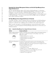
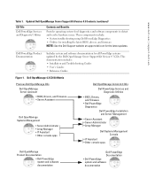
...-to version 4.3. Use Figure 1 to install and manage your Dell documentation. These tools and applications include: • Dell OpenManage IT Assistant • Array Manager Console • Dell Remote Access Controller (DRAC) Console • Baseboard Management Controller (BMC) Remote Console • Dell Management Information Base (MIB) • Additional console applications Updated Dell OpenManage Server Support Kit Version 4.3 Contents CD Title Contents and Benefits Dell PowerEdge Installation Includes an operating system installation utility and all required software and Server...
...-to version 4.3. Use Figure 1 to install and manage your Dell documentation. These tools and applications include: • Dell OpenManage IT Assistant • Array Manager Console • Dell Remote Access Controller (DRAC) Console • Baseboard Management Controller (BMC) Remote Console • Dell Management Information Base (MIB) • Additional console applications Updated Dell OpenManage Server Support Kit Version 4.3 Contents CD Title Contents and Benefits Dell PowerEdge Installation Includes an operating system installation utility and all required software and Server...
Upgrade the BIOS Before Upgrading Your System (.pdf)
Page 3
...CD Title Dell PowerEdge Services and Diagnostic Utilities Contents and Benefits Provides operating system-level diagnostics and software components to detect and resolve hardware issues. Dell PowerEdge Product Documentation Includes system and software documentation for the latest updates. These components include: • System troubleshooting using Dell PowerEdge Diagnostics • Utilities for installing the latest BIOS, drivers, and firmware NOTE: See the Dell Support website at support.dell.com for all PowerEdge systems updated by the Dell OpenManage Server Support Kit Version...
...CD Title Dell PowerEdge Services and Diagnostic Utilities Contents and Benefits Provides operating system-level diagnostics and software components to detect and resolve hardware issues. Dell PowerEdge Product Documentation Includes system and software documentation for the latest updates. These components include: • System troubleshooting using Dell PowerEdge Diagnostics • Utilities for installing the latest BIOS, drivers, and firmware NOTE: See the Dell Support website at support.dell.com for all PowerEdge systems updated by the Dell OpenManage Server Support Kit Version...
Upgrade the BIOS Before Upgrading Your System (.pdf)
Page 5
...;本 4.3 Server Support Kit Dell OpenManage 版本 4.3 Dell™ Server Update Utility Dell OpenManage Server Support Kit 版本 4.3 升级 Dell OpenManage Systems Management Software •Dell OpenManage Server Support Kit 版本 4.3 内容 Dell OpenManage 版本 4.3 Dell OpenManage Server Support Kit 版本 4.3 Dell PowerEdge Microsoft® Installer Utility [MSI]、Red Hat® Package Manger [RPM] 和 Novell® IPS Microsoft Windows PowerEdge Dell OpenManage Service Pack Dell OpenManage...
...;本 4.3 Server Support Kit Dell OpenManage 版本 4.3 Dell™ Server Update Utility Dell OpenManage Server Support Kit 版本 4.3 升级 Dell OpenManage Systems Management Software •Dell OpenManage Server Support Kit 版本 4.3 内容 Dell OpenManage 版本 4.3 Dell OpenManage Server Support Kit 版本 4.3 Dell PowerEdge Microsoft® Installer Utility [MSI]、Red Hat® Package Manger [RPM] 和 Novell® IPS Microsoft Windows PowerEdge Dell OpenManage Service Pack Dell OpenManage...
Upgrade the BIOS Before Upgrading Your System (.pdf)
Page 17
....dell.com Dell OpenManage Server Support Kit 4.3 Dell OpenManage 4.3 Server Support Kit Dell OpenManage 4.3 Dell™ Server Update Utility Dell OpenManage Server Support Kit 4.3 による OpenManage Systems Management Software Dell OpenManage Server Support Kit 4.3 の目次 Dell OpenManage 4.3 Dell OpenManage 4.3 は、Systems Management Software を Dell PowerEdge Microsoft® Installer Utility [MSI]、Red Hat® Package Manger [RPM Novell® IPS Microsoft Windows PowerEdge Dell OpenManage Service Pack Dell...
....dell.com Dell OpenManage Server Support Kit 4.3 Dell OpenManage 4.3 Server Support Kit Dell OpenManage 4.3 Dell™ Server Update Utility Dell OpenManage Server Support Kit 4.3 による OpenManage Systems Management Software Dell OpenManage Server Support Kit 4.3 の目次 Dell OpenManage 4.3 Dell OpenManage 4.3 は、Systems Management Software を Dell PowerEdge Microsoft® Installer Utility [MSI]、Red Hat® Package Manger [RPM Novell® IPS Microsoft Windows PowerEdge Dell OpenManage Service Pack Dell...
Activating the Integrated RAID Controller (.pdf)
Page 1
...; 2004 Dell Inc. www.dell.com | support.dell.com Updating Dell™ Diagnostics This document provides information about resolving an issue when using a USB keyboard connected to the front-panel USB connector and running Dell diagnostics with a USB keyboard, use the front-panel USB connector with the keyboard, download the latest diagnostics from the Dell Support website at support.dell.com. To use the back-panel USB connector. Other trademarks and trade names may be used in this document to refer to change without the...
...; 2004 Dell Inc. www.dell.com | support.dell.com Updating Dell™ Diagnostics This document provides information about resolving an issue when using a USB keyboard connected to the front-panel USB connector and running Dell diagnostics with a USB keyboard, use the front-panel USB connector with the keyboard, download the latest diagnostics from the Dell Support website at support.dell.com. To use the back-panel USB connector. Other trademarks and trade names may be used in this document to refer to change without the...
Processor Upgrade Installation Guide
Page 5
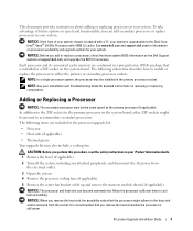
... cache. Allow the processor sufficient time to accommodate secondary processors. Processor Upgrade Installation Guide 3 This document provides instructions about adding or replacing processors in the processor upgrade kit: • Processor • Heat sink (if applicable) • Thermal grease Your upgrade kit may also include a cooling fan. See www.dell.com and support.dell.com for information on processor availability and upgrade options for your Installation and Troubleshooting Guide for the primary processor on the system board. NOTE: See...
... cache. Allow the processor sufficient time to accommodate secondary processors. Processor Upgrade Installation Guide 3 This document provides instructions about adding or replacing processors in the processor upgrade kit: • Processor • Heat sink (if applicable) • Thermal grease Your upgrade kit may also include a cooling fan. See www.dell.com and support.dell.com for information on processor availability and upgrade options for your Installation and Troubleshooting Guide for the primary processor on the system board. NOTE: See...
Processor Upgrade Installation Guide
Page 7
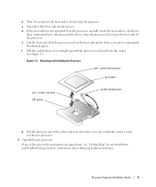
... the socket is released from the processor, carefully rotate the heat sink in your Installation and Troubleshooting Guide for instructions about obtaining technical assistance. Processor Upgrade Installation Guide 5 Figure 1-2. b Wait 30 seconds for the heat sink to contaminate the thermal grease. d If the heat sink has not separated from the socket. e Lift the heat sink off the processor. c Open the other heat-sink retention lever. If any...
... the socket is released from the processor, carefully rotate the heat sink in your Installation and Troubleshooting Guide for instructions about obtaining technical assistance. Processor Upgrade Installation Guide 5 Figure 1-2. b Wait 30 seconds for the heat sink to contaminate the thermal grease. d If the heat sink has not separated from the socket. e Lift the heat sink off the processor. c Open the other heat-sink retention lever. If any...
Processor Upgrade Installation Guide
Page 8
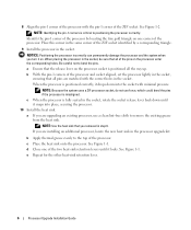
... socket aligned, set the processor lightly in the processor upgrade kit. a Ensure that you are matched with the correct holes in the socket. b With the pin-1 corners of the processor by a corresponding triangle. 9 Install the processor in the socket. NOTE: Because the system uses a ZIF processor socket, do not use a clean lint-free cloth to bend the pins. NOTE: Use the heat sink that...
... socket aligned, set the processor lightly in the processor upgrade kit. a Ensure that you are matched with the correct holes in the socket. b With the pin-1 corners of the processor by a corresponding triangle. 9 Install the processor in the socket. NOTE: Because the system uses a ZIF processor socket, do not use a clean lint-free cloth to bend the pins. NOTE: Use the heat sink that...
Processor Upgrade Installation Guide
Page 9
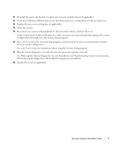
... system boots, it detects the presence of the new processor and automatically changes the system configuration information in your Installation and Troubleshooting Guide for information about using the System Setup program. 17 Run the system diagnostics to their electrical outlets, and turn them on. 11 Reinstall the center fan bracket or replace the memory module shroud (if applicable). 12 If you have added an additional processor, install the processor cooling fan...
... system boots, it detects the presence of the new processor and automatically changes the system configuration information in your Installation and Troubleshooting Guide for information about using the System Setup program. 17 Run the system diagnostics to their electrical outlets, and turn them on. 11 Reinstall the center fan bracket or replace the memory module shroud (if applicable). 12 If you have added an additional processor, install the processor cooling fan...
Activating the Integrated RAID Controller
Page 5
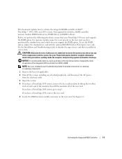
... electrostatic discharge. Activating the Integrated RAID Controller 1-3 NOTICE: To avoid possible data loss, back up all data on Dell™ PowerEdge™ 1850, 2800, and 2850 systems. Your upgrade kit includes a RAID controller memory module, RAID hardware key, RAID battery, and RAID software. See the Installation and Troubleshooting Guide to step 5. To use the RAID option, replace the standard riser card with the optional ROMB PCI-X or PCI-Express riser card. See your PowerEdge 1850 riser card supports the RAID option. If you have...
... electrostatic discharge. Activating the Integrated RAID Controller 1-3 NOTICE: To avoid possible data loss, back up all data on Dell™ PowerEdge™ 1850, 2800, and 2850 systems. Your upgrade kit includes a RAID controller memory module, RAID hardware key, RAID battery, and RAID software. See the Installation and Troubleshooting Guide to step 5. To use the RAID option, replace the standard riser card with the optional ROMB PCI-X or PCI-Express riser card. See your PowerEdge 1850 riser card supports the RAID option. If you have...
Activating the Integrated RAID Controller
Page 7
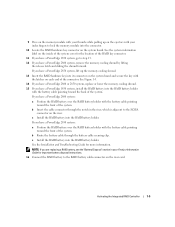
.... c Install the RAID battery into the RAID battery holder. Activating the Integrated RAID Controller 1-5 If you have a PowerEdge 2850 system, lift up on the ejectors with your Product Information Guide for important battery disposal instructions. 16 Connect the RAID battery to the RAID battery cable connector on the inside of the system cover for more information. b Insert the cable connector through the battery cable securing clip. See the Installation and Troubleshooting Guide for the location of the RAID key connector. 11...
.... c Install the RAID battery into the RAID battery holder. Activating the Integrated RAID Controller 1-5 If you have a PowerEdge 2850 system, lift up on the ejectors with your Product Information Guide for important battery disposal instructions. 16 Connect the RAID battery to the RAID battery cable connector on the inside of the system cover for more information. b Insert the cable connector through the battery cable securing clip. See the Installation and Troubleshooting Guide for the location of the RAID key connector. 11...
Activating the Integrated RAID Controller
Page 8
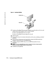
... a PowerEdge 2850 system, replace the riser card. 18 Close the system. 19 Reconnect the system to its electrical outlet and turn on the two plastic rivets to 4 hours of the RAID hardware. 21 Install and configure the RAID software. NOTICE: The newly-installed RAID battery must be charged for more information. www.dell.com | support.dell.com Figure 1-3. See your RAID documentation for 3 to secure the insulator. Installing the RAID Key hardware key latches...
... a PowerEdge 2850 system, replace the riser card. 18 Close the system. 19 Reconnect the system to its electrical outlet and turn on the two plastic rivets to 4 hours of the RAID hardware. 21 Install and configure the RAID software. NOTICE: The newly-installed RAID battery must be charged for more information. www.dell.com | support.dell.com Figure 1-3. See your RAID documentation for 3 to secure the insulator. Installing the RAID Key hardware key latches...
Updating Your NIC Teaming Drivers (.pdf)
Page 3
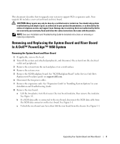
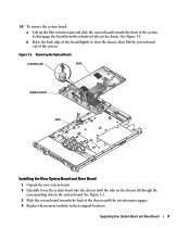
... connected to support PCI-e expansion cards. Removing and Replacing the System Board and Riser Board In A Dell™ PowerEdge™ 1850 System Removing the System Board and Riser Board 1 If applicable, remove the bezel. 2 Turn off the system and attached peripherals, and disconnect the system from the electrical outlet and peripherals. 3 Remove the system from the chassis. See "SCSI Backplane Board" in the Service-Only Parts Replacement Procedures guide on removing or replacing components. b If a SCSI data cable is not covered...
... connected to support PCI-e expansion cards. Removing and Replacing the System Board and Riser Board In A Dell™ PowerEdge™ 1850 System Removing the System Board and Riser Board 1 If applicable, remove the bezel. 2 Turn off the system and attached peripherals, and disconnect the system from the electrical outlet and peripherals. 3 Remove the system from the chassis. See "SCSI Backplane Board" in the Service-Only Parts Replacement Procedures guide on removing or replacing components. b If a SCSI data cable is not covered...
Updating Your NIC Teaming Drivers (.pdf)
Page 4
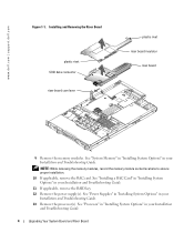
... power supply(s). See "System Memory" in "Installing System Options" in your Installation and Troubleshooting Guide. See "Processor" in "Installing System Options" in your Installation and Troubleshooting Guide. 4 Upgrading Your System Board and Riser Board See "Power Supplies" in "Installing System Options" in your Installation and Troubleshooting Guide. 13 Remove the processor(s). Installing and Removing the Riser Board plastic rivet SCSI data connector riser board cam lever plastic rivet riser board insulator riser board 9 Remove the memory modules. www.dell.com | support...
... power supply(s). See "System Memory" in "Installing System Options" in your Installation and Troubleshooting Guide. See "Processor" in "Installing System Options" in your Installation and Troubleshooting Guide. 4 Upgrading Your System Board and Riser Board See "Power Supplies" in "Installing System Options" in your Installation and Troubleshooting Guide. 13 Remove the processor(s). Installing and Removing the Riser Board plastic rivet SCSI data connector riser board cam lever plastic rivet riser board insulator riser board 9 Remove the memory modules. www.dell.com | support...
Updating Your NIC Teaming Drivers (.pdf)
Page 5
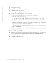
... slots system board tabs Installing the New System Board and Riser Board 1 Unpack the new system board. 2 Carefully lower the system board into the chassis until the retention pin engages. 4 Replace the memory modules in the system board. See Figure 1-2. b Raise the back edge of the board slightly to disengage the board from the retention tabs on the chassis fit through the corresponding slots in their original locations. Upgrading...
... slots system board tabs Installing the New System Board and Riser Board 1 Unpack the new system board. 2 Carefully lower the system board into the chassis until the retention pin engages. 4 Replace the memory modules in the system board. See Figure 1-2. b Raise the back edge of the board slightly to disengage the board from the retention tabs on the chassis fit through the corresponding slots in their original locations. Upgrading...
Updating Your NIC Teaming Drivers (.pdf)
Page 6
... SCSI data cable while removing the riser board, reconnect the cable to secure the insulator. 11 Reconnect the fan power cables. 12 Replace the SCSI backplane board and reinstall the SCSI hard drives. www.dell.com | support.dell.com 5 Replace the processor(s). 6 If applicable, replace the RAC card. 7 If applicable, replace the RAID key. 8 Replace the power supply(s). 9 Install the new riser board provided in the Service-Only Parts Replacement Procedures guide on the two plastic rivets to the riser board. 10 Place the plastic riser board...
... SCSI data cable while removing the riser board, reconnect the cable to secure the insulator. 11 Reconnect the fan power cables. 12 Replace the SCSI backplane board and reinstall the SCSI hard drives. www.dell.com | support.dell.com 5 Replace the processor(s). 6 If applicable, replace the RAC card. 7 If applicable, replace the RAID key. 8 Replace the power supply(s). 9 Install the new riser board provided in the Service-Only Parts Replacement Procedures guide on the two plastic rivets to the riser board. 10 Place the plastic riser board...
Updating Your NIC Teaming Drivers (.pdf)
Page 7
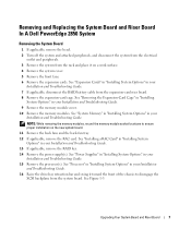
... Installation and Troubleshooting Guide. 15 Remove the processor(s). NOTE: While removing the memory modules, record the memory module socket locations to disengage the SCSI backplane from the rack and place it toward the front of the chassis to ensure proper installation on a work surface. 4 Remove the system cover. 5 Remove the front fans. 6 Remove the expansion cards. See "Removing the Expansion-Card Cage" in "Installing System Options" in your Installation and Troubleshooting Guide. 13 If applicable, remove the RAID key. 14 Remove the power supply(s). Upgrading Your System Board...
... Installation and Troubleshooting Guide. 15 Remove the processor(s). NOTE: While removing the memory modules, record the memory module socket locations to disengage the SCSI backplane from the rack and place it toward the front of the chassis to ensure proper installation on a work surface. 4 Remove the system cover. 5 Remove the front fans. 6 Remove the expansion cards. See "Removing the Expansion-Card Cage" in "Installing System Options" in your Installation and Troubleshooting Guide. 13 If applicable, remove the RAID key. 14 Remove the power supply(s). Upgrading Your System Board...
Updating Your NIC Teaming Drivers (.pdf)
Page 9
... 1-3. 7 Replace the memory modules. 8 Replace the memory module cover. 9 Replace the processor(s). 10 If applicable, replace the RAC card. 11 If applicable, replace the RAID key. 12 Replace the back-fan tray and the back fans. 13 Replace the power supply(s). 14 Replace the riser board in your Installation and Troubleshooting Guide. 16 If applicable, reconnect the RAID battery cable to the left until it is completely flush with the new riser board. See "Upgrading the Dell PowerEdge 2850 Expansion-Card Riser Board." 15 Reinstall the expansion-card...
... 1-3. 7 Replace the memory modules. 8 Replace the memory module cover. 9 Replace the processor(s). 10 If applicable, replace the RAC card. 11 If applicable, replace the RAID key. 12 Replace the back-fan tray and the back fans. 13 Replace the power supply(s). 14 Replace the riser board in your Installation and Troubleshooting Guide. 16 If applicable, reconnect the RAID battery cable to the left until it is completely flush with the new riser board. See "Upgrading the Dell PowerEdge 2850 Expansion-Card Riser Board." 15 Reinstall the expansion-card...
Updating Your NIC Teaming Drivers (.pdf)
Page 10
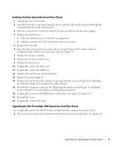
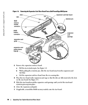
... card openings until you feel the riser-board retention pin snap into place. 6 Close the expansion-card guide. 7 If applicable, reinstall the RAID memory module onto the riser board. 10 Upgrading Your System Board and Riser Board Removing the Expansion-Card Riser Board From a Dell PowerEdge 2850 System slots tabs RAID memory module connector expansion-card riser board retention pin RAID battery connector expansion-card guide expansion card openings expansion-card guide release tabs (2) 3 Remove the expansion-card riser board: a Pull the riser retention pin. www.dell.com | support...
... card openings until you feel the riser-board retention pin snap into place. 6 Close the expansion-card guide. 7 If applicable, reinstall the RAID memory module onto the riser board. 10 Upgrading Your System Board and Riser Board Removing the Expansion-Card Riser Board From a Dell PowerEdge 2850 System slots tabs RAID memory module connector expansion-card riser board retention pin RAID battery connector expansion-card guide expansion card openings expansion-card guide release tabs (2) 3 Remove the expansion-card riser board: a Pull the riser retention pin. www.dell.com | support...


