
SCSI Backplane Daughter Card (.pdf)
Page 1
™ Dell™ PowerEdge™ 2450 Systems INSTALLING A FIFTH SCSI HARD-DISK DRIVE www.dell.com
™ Dell™ PowerEdge™ 2450 Systems INSTALLING A FIFTH SCSI HARD-DISK DRIVE www.dell.com

SCSI Backplane Daughter Card (.pdf)
Page 3
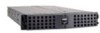
... interposer card peripheral bay Figure 1-1. Dell™ PowerEdge™ 2450 Systems Installing a Fifth SCSI Hard-Disk Drive This document describes installing and configuring an optional fifth small computer system interface (SCSI) hard-disk drive in your computer's peripheral bay. Basic SCSI Hard-Disk Drive System Components support.dell.com Dell PowerEdge 2450 Systems - If you should install...
... interposer card peripheral bay Figure 1-1. Dell™ PowerEdge™ 2450 Systems Installing a Fifth SCSI Hard-Disk Drive This document describes installing and configuring an optional fifth small computer system interface (SCSI) hard-disk drive in your computer's peripheral bay. Basic SCSI Hard-Disk Drive System Components support.dell.com Dell PowerEdge 2450 Systems - If you should install...

SCSI Backplane Daughter Card (.pdf)
Page 4
...SCSI ID 3 (see Figure 1-1). Hard-Disk Drive Configuration The four hard-disk drives connected to the main SCSI backplane board are supplied by Dell in special drive carriers that fit in the harddisk drive bays. To operate the five drives in a 1 x 5 configuration, attach a ... from the drive. 5. For a drive carrier to the interposer board on the SCSI backplane board. For more information, see Figure 1-2). 1-2 Dell PowerEdge 2450 Systems - Disconnect all cables connected to fit in your computer. 1. These cables include the system board interface cable, cooling fan wiring harness, ...
...SCSI ID 3 (see Figure 1-1). Hard-Disk Drive Configuration The four hard-disk drives connected to the main SCSI backplane board are supplied by Dell in special drive carriers that fit in the harddisk drive bays. To operate the five drives in a 1 x 5 configuration, attach a ... from the drive. 5. For a drive carrier to the interposer board on the SCSI backplane board. For more information, see Figure 1-2). 1-2 Dell PowerEdge 2450 Systems - Disconnect all cables connected to fit in your computer. 1. These cables include the system board interface cable, cooling fan wiring harness, ...

SCSI Backplane Daughter Card (.pdf)
Page 5
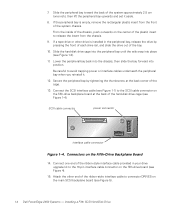
Installing a Fifth SCSI Hard-Disk Drive 1-3 thumbscrew hard-disk drive cage rails (2) peripheral bay Figure 1-3. Connectors on the Interposer Board 6. Loosen the thumbscrew at the back corner of the peripheral bay (see Figure 1-3). cooling fan wiring harness connector system board interface cable connector interposer board power cable connector control panel cable connector diskette drive/CD-ROM drive interface connector Figure 1-2. Installing the Hard-Disk Drive Cage in the Peripheral Bay support.dell.com Dell PowerEdge 2450 Systems -
Installing a Fifth SCSI Hard-Disk Drive 1-3 thumbscrew hard-disk drive cage rails (2) peripheral bay Figure 1-3. Connectors on the Interposer Board 6. Loosen the thumbscrew at the back corner of the peripheral bay (see Figure 1-3). cooling fan wiring harness connector system board interface cable connector interposer board power cable connector control panel cable connector diskette drive/CD-ROM drive interface connector Figure 1-2. Installing the Hard-Disk Drive Cage in the Peripheral Bay support.dell.com Dell PowerEdge 2450 Systems -
SCSI Backplane Daughter Card (.pdf)
Page 6
... front of the cage. 13. Installing a Fifth SCSI Hard-Disk Drive If a tape drive or other end of the hard-disk drive cage (see Figure 5). 1-4 Dell PowerEdge 2450 Systems - Secure the peripheral bay by pressing the front of each drive rail, and slide the drive out of the chassis, push outwards on the...
... front of the cage. 13. Installing a Fifth SCSI Hard-Disk Drive If a tape drive or other end of the hard-disk drive cage (see Figure 5). 1-4 Dell PowerEdge 2450 Systems - Secure the peripheral bay by pressing the front of each drive rail, and slide the drive out of the chassis, push outwards on the...

SCSI Backplane Daughter Card (.pdf)
Page 7
... the front of the hard-disk drive cage, and insert the carrier into the drive cage (see Figure 4). 17. SCSI Hard-Disk Drive Carrier support.dell.com Dell PowerEdge 2450 Systems - Connectors on the fifth-drive backplane board (see Figure 1-6). Connect the spare power cable leading from the power supply distribution board (see Figure...
... the front of the hard-disk drive cage, and insert the carrier into the drive cage (see Figure 4). 17. SCSI Hard-Disk Drive Carrier support.dell.com Dell PowerEdge 2450 Systems - Connectors on the fifth-drive backplane board (see Figure 1-6). Connect the spare power cable leading from the power supply distribution board (see Figure...

SCSI Backplane Daughter Card (.pdf)
Page 8
... bezel in your Installation and Troubleshooting Guide. 1-6 Dell PowerEdge 2450 Systems - 19. Arrange cables so that may have been loosened during this installation procedure. Close the hard-disk drive carrier handle to lock the drive carrier in place (see "Running the Dell Diagnostics" in step 3, reinstall it. 21. If... the hard-disk drive is a new drive, run the Dell Diagnostics to their AC power sources, and turn them on the computer covers or block...
... bezel in your Installation and Troubleshooting Guide. 1-6 Dell PowerEdge 2450 Systems - 19. Arrange cables so that may have been loosened during this installation procedure. Close the hard-disk drive carrier handle to lock the drive carrier in place (see "Running the Dell Diagnostics" in step 3, reinstall it. 21. If... the hard-disk drive is a new drive, run the Dell Diagnostics to their AC power sources, and turn them on the computer covers or block...

Activating the Dell PERC 3/Si (.pdf)
Page 3
...the cage must be placed upon removal from the electrical outlet. 2. Prepare the expansion card for your system. 3. support.dell.com Dell PowerEdge 2450 Systems Information Update 1-1 Check any cables that came with the expansion card for information on the following topics for installation, and... updates information on configuring the card, making internal connections, or otherwise customizing the card for your Dell PowerEdge 2450 system: Installing and removing expansion cards Small computer system interface (SCSI) hard-disk drive support Installing an upgrade microprocessor in...
...the cage must be placed upon removal from the electrical outlet. 2. Prepare the expansion card for your system. 3. support.dell.com Dell PowerEdge 2450 Systems Information Update 1-1 Check any cables that came with the expansion card for information on the following topics for installation, and... updates information on configuring the card, making internal connections, or otherwise customizing the card for your Dell PowerEdge 2450 system: Installing and removing expansion cards Small computer system interface (SCSI) hard-disk drive support Installing an upgrade microprocessor in...

Activating the Dell PERC 3/Si (.pdf)
Page 4
Lift the expansion-card cage up and away from the expansion slot. Rotate the lever upward until it stops in an upright position. 5. Open the expansion-card latch (see Figure 1-1). expansion-card latch expansion card card-edge connector expansion-card connector riser board 1-2 Dell PowerEdge 2450 Systems Information Update card guide expansion-card cage securing lever expansion-card cage 4. Locate the expansion-card cage securing lever (see Figure 1-2) and remove the filler bracket from the chassis. 6.
Lift the expansion-card cage up and away from the expansion slot. Rotate the lever upward until it stops in an upright position. 5. Open the expansion-card latch (see Figure 1-1). expansion-card latch expansion card card-edge connector expansion-card connector riser board 1-2 Dell PowerEdge 2450 Systems Information Update card guide expansion-card cage securing lever expansion-card cage 4. Locate the expansion-card cage securing lever (see Figure 1-2) and remove the filler bracket from the chassis. 6.

Activating the Dell PERC 3/Si (.pdf)
Page 5
... and peripherals to their AC power sources and turn them on the system board. 12. Grasp the expansion card by its cable connections. 13. support.dell.com Dell PowerEdge 2450 Systems Information Update 1-3 Rotate the securing lever downward until it , close the expansion-card latch. 9. Insert the card-edge connector firmly into place until...
... and peripherals to their AC power sources and turn them on the system board. 12. Grasp the expansion card by its cable connections. 13. support.dell.com Dell PowerEdge 2450 Systems Information Update 1-3 Rotate the securing lever downward until it , close the expansion-card latch. 9. Insert the card-edge connector firmly into place until...

Activating the Dell PERC 3/Si (.pdf)
Page 6
... Selections are interchangeable. This section provides instructions for your Dell PowerEdge 2450 Systems User's Guide have been combined to Off, Channel A and Channel B display Off. Before you perform any devices. 1-4 Dell PowerEdge 2450 Systems Information Update When you set it to slide in...to RAID Enabled, Channel A displays RAID and Channel B displays SCSI. The Ultra3 SCSI standard supports a combination of the Dell PowerEdge 2450 Systems Installation and Troubleshooting Guide, make sure to SCSI Enabled, Channel A and Channel B display SCSI. Your system employs an...
... Selections are interchangeable. This section provides instructions for your Dell PowerEdge 2450 Systems User's Guide have been combined to Off, Channel A and Channel B display Off. Before you perform any devices. 1-4 Dell PowerEdge 2450 Systems Information Update When you set it to slide in...to RAID Enabled, Channel A displays RAID and Channel B displays SCSI. The Ultra3 SCSI standard supports a combination of the Dell PowerEdge 2450 Systems Installation and Troubleshooting Guide, make sure to SCSI Enabled, Channel A and Channel B display SCSI. Your system employs an...

Activating the Dell PERC 3/Si (.pdf)
Page 7
Use the resource configuration utility (RCU) diskette to save the RCU configuration settings (see your system. support.dell.com Dell PowerEdge 2450 Systems Information Update 1-5 2. Hold a card by its edges or by its pins. Also, disconnect any telephone or telecommunication lines from their power sources. Doing so ...
Use the resource configuration utility (RCU) diskette to save the RCU configuration settings (see your system. support.dell.com Dell PowerEdge 2450 Systems Information Update 1-5 2. Hold a card by its edges or by its pins. Also, disconnect any telephone or telecommunication lines from their power sources. Doing so ...

Activating the Dell PERC 3/Si (.pdf)
Page 8
... appears. Select Step 5: Save and Exit, and then follow the online instructions to save the current system configuration information. 1-6 Dell PowerEdge 2450 Systems Information Update Follow the instructions on the screen to reboot the system. Use the RCU diskette provided with the kit to save...update your ESM firmware with the version contained on the screen. 4. The latest version of the BIOS is available at http://support.dell.com. 1. Insert the ESM firmware diskette into the diskette drive. 2. The message appears on that diskette by performing the following steps...
... appears. Select Step 5: Save and Exit, and then follow the online instructions to save the current system configuration information. 1-6 Dell PowerEdge 2450 Systems Information Update Follow the instructions on the screen to reboot the system. Use the RCU diskette provided with the kit to save...update your ESM firmware with the version contained on the screen. 4. The latest version of the BIOS is available at http://support.dell.com. 1. Insert the ESM firmware diskette into the diskette drive. 2. The message appears on that diskette by performing the following steps...

Activating the Dell PERC 3/Si (.pdf)
Page 9
a. c. support.dell.com Dell PowerEdge 2450 Systems Information Update 1-7 NOTE: The RCU recognizes microprocessors operating at http://support.dell.com. 1. Push firmly on the outside of the power supply enclosure beside the narrower front part of the air blower upward and away from the ...
a. c. support.dell.com Dell PowerEdge 2450 Systems Information Update 1-7 NOTE: The RCU recognizes microprocessors operating at http://support.dell.com. 1. Push firmly on the outside of the power supply enclosure beside the narrower front part of the air blower upward and away from the ...

Activating the Dell PERC 3/Si (.pdf)
Page 10
air blower power supply enclosure tab slot air blower power cable 4. a. Then lift the SEC cartridge and heat sink away from the end of the heat sink and pull up slightly on the heat sink. Pull the tab on one side of the guide-bracket assembly to disengage the tab on the SEC cartridge and heat sink (see Figure 1-4). 1-8 Dell PowerEdge 2450 Systems Information Update b. Remove the SEC cartridge and heat sink as follows. Pull the tab on the other end of the guide-bracket assembly away from the guide-bracket assembly (see Figure 1-4).
air blower power supply enclosure tab slot air blower power cable 4. a. Then lift the SEC cartridge and heat sink away from the end of the heat sink and pull up slightly on the heat sink. Pull the tab on one side of the guide-bracket assembly to disengage the tab on the SEC cartridge and heat sink (see Figure 1-4). 1-8 Dell PowerEdge 2450 Systems Information Update b. Remove the SEC cartridge and heat sink as follows. Pull the tab on the other end of the guide-bracket assembly away from the guide-bracket assembly (see Figure 1-4).

Activating the Dell PERC 3/Si (.pdf)
Page 11
support.dell.com Dell PowerEdge 2450 Systems Information Update 1-9 Slide the SEC cartridge and heat sink into the guide-bracket assembly and firmly seat them in the assembly until the tabs snap into place over the ends of the heat sink (see Figure 1-5). heat sink guide-bracket assembly SEC cartridge tab 1.
support.dell.com Dell PowerEdge 2450 Systems Information Update 1-9 Slide the SEC cartridge and heat sink into the guide-bracket assembly and firmly seat them in the assembly until the tabs snap into place over the ends of the heat sink (see Figure 1-5). heat sink guide-bracket assembly SEC cartridge tab 1.

Activating the Dell PERC 3/Si (.pdf)
Page 12
... narrower front part of the chassis. e. With your left hand, push down and toward the power supplies, allowing extra clearance to their power sources. 1-10 Dell PowerEdge 2450 Systems Information Update if it is level; Reconnect your right thumb on the front of the chassis. b. Push firmly on the interposer board. 3. d. g. Make sure...
... narrower front part of the chassis. e. With your left hand, push down and toward the power supplies, allowing extra clearance to their power sources. 1-10 Dell PowerEdge 2450 Systems Information Update if it is level; Reconnect your right thumb on the front of the chassis. b. Push firmly on the interposer board. 3. d. g. Make sure...

Installation and Troubleshooting Guide (.pdf)
Page 3
...to the ceiling or upper wall, and where applicable, to the system and personal injury may result. Preliminary 9/27/01 Dell PowerEdge 2450 Systems - Two-Post Rack Installation 1 The two-post open -frame relay rack manufacturer's installation documentation for additional safety ...information regarding rack installation. (Rev. 11/3/98) FILE LOCATION: C:\Dell\docs\2450\2post\81HFFts0.fm Dell™ PowerEdge™ 2450 Systems Two-Post Rack Installation This document provides instructions for installing a Dell PowerEdge 2450 system in a two-post open -frame relay rack that has not...
...to the ceiling or upper wall, and where applicable, to the system and personal injury may result. Preliminary 9/27/01 Dell PowerEdge 2450 Systems - Two-Post Rack Installation 1 The two-post open -frame relay rack manufacturer's installation documentation for additional safety ...information regarding rack installation. (Rev. 11/3/98) FILE LOCATION: C:\Dell\docs\2450\2post\81HFFts0.fm Dell™ PowerEdge™ 2450 Systems Two-Post Rack Installation This document provides instructions for installing a Dell PowerEdge 2450 system in a two-post open -frame relay rack that has not...

Installation and Troubleshooting Guide (.pdf)
Page 4
... of a 1-U space) of the 2-U support tray. 2. Two-Post Rack Installation DELL CONFIDENTIAL - Each 1-U (1.75-inch) vertical space has three holes, with center-to be used Marking the Rack 1. Preliminary 9/27/01 2 Dell PowerEdge 2450 Systems - Determine where you want to place the bottom of 0.625, 0.625, ...and 0.5 inches (see Figure 2). Mark the top and bottom holes on the rack. (Rev. 11/3/98) FILE LOCATION: C:\Dell\docs\2450\2post\81HFFts0.fm tray assembly 12-24...
... of a 1-U space) of the 2-U support tray. 2. Two-Post Rack Installation DELL CONFIDENTIAL - Each 1-U (1.75-inch) vertical space has three holes, with center-to be used Marking the Rack 1. Preliminary 9/27/01 2 Dell PowerEdge 2450 Systems - Determine where you want to place the bottom of 0.625, 0.625, ...and 0.5 inches (see Figure 2). Mark the top and bottom holes on the rack. (Rev. 11/3/98) FILE LOCATION: C:\Dell\docs\2450\2post\81HFFts0.fm tray assembly 12-24...

Installation and Troubleshooting Guide (.pdf)
Page 5
...and the bottom holes on the front of the PowerEdge server. support.dell.com DELL CONFIDENTIAL - Install four 12-24 x 0.5-inch screws provided to the system and personal injury may result. 1. Preliminary 9/27/01 Dell PowerEdge 2450 Systems - Two-Post Open-Frame Relay Rack 1-U... Hole Spacing Installing the Support Tray in this support tray. Two-Post Rack Installation 3 (Rev. 11/3/98) FILE LOCATION: C:\Dell\docs\2450\2post\81HFFts0.fm 3.5 inches (2 U) 1.75 inch...
...and the bottom holes on the front of the PowerEdge server. support.dell.com DELL CONFIDENTIAL - Install four 12-24 x 0.5-inch screws provided to the system and personal injury may result. 1. Preliminary 9/27/01 Dell PowerEdge 2450 Systems - Two-Post Open-Frame Relay Rack 1-U... Hole Spacing Installing the Support Tray in this support tray. Two-Post Rack Installation 3 (Rev. 11/3/98) FILE LOCATION: C:\Dell\docs\2450\2post\81HFFts0.fm 3.5 inches (2 U) 1.75 inch...


