
Configuration Guide
Page 9
...fully booted and ready to send packets. 3 Connect the keyboard, video, and mouse to the KVM module. NOTE: You should power up the enclosure prior to the power supplies. NOTE: Always ...to configure and install these options. • Updates are installed. Figure 1-3 shows the basic cabling configuration for experienced users or technicians. General System Configuration 7 • The Baseboard Management Controller documentation ... on the systems management software applications, as well as information on support.dell.com and read the updates first because they often supersede information in a...
...fully booted and ready to send packets. 3 Connect the keyboard, video, and mouse to the KVM module. NOTE: You should power up the enclosure prior to the power supplies. NOTE: Always ...to configure and install these options. • Updates are installed. Figure 1-3 shows the basic cabling configuration for experienced users or technicians. General System Configuration 7 • The Baseboard Management Controller documentation ... on the systems management software applications, as well as information on support.dell.com and read the updates first because they often supersede information in a...

Configuration Guide
Page 10
... module configured for RAID 1, the drives in the server module System Setup program. Figure 1-3. See "Configuring Drive Mirroring" on page 9 for RAID 1 or integrated mirroring. KVM Module Basic Configuration 1 6 5 2 4 3 1 monitor 4 DRAC/MC module 2 custom KVM cable 5 mouse 3 KVM module 6 keyboard 4 If required, configure the hard drives for more information.
... module configured for RAID 1, the drives in the server module System Setup program. Figure 1-3. See "Configuring Drive Mirroring" on page 9 for RAID 1 or integrated mirroring. KVM Module Basic Configuration 1 6 5 2 4 3 1 monitor 4 DRAC/MC module 2 custom KVM cable 5 mouse 3 KVM module 6 keyboard 4 If required, configure the hard drives for more information.

Configuration Guide
Page 35
... connector for the two KVM switch modules supported by Dell PowerEdge 1955 server modules (blades). NOTE: The Avocent Analog KVM switch ACI port can only be used on Dell console switches, with that switch. Figure 2-1. the Avocent Analog KVM switch module (Figure 2-1) and Avocent Digital Access KVM switch module (Figure 2-2). NOTICE: The basic Dell™ KVM pass-though module used...
... connector for the two KVM switch modules supported by Dell PowerEdge 1955 server modules (blades). NOTE: The Avocent Analog KVM switch ACI port can only be used on Dell console switches, with that switch. Figure 2-1. the Avocent Analog KVM switch module (Figure 2-1) and Avocent Digital Access KVM switch module (Figure 2-2). NOTICE: The basic Dell™ KVM pass-though module used...

Configuration Guide
Page 36
... (see Figure 2-1) to an external Dell analog or digital KVM switch. Figure 2-2. See "Configuring a KVM Using the OSCAR Interface and Direct Access" on the KVM (see Figure 2-2), and use the OSCAR interface. Avocent Digital Access KVM Switch Module 1 2 1 RJ-45 connector (Ethernet interface) 2 custom connector (for custom KVM cable - The Analog KVM module can be configured using the...
... (see Figure 2-1) to an external Dell analog or digital KVM switch. Figure 2-2. See "Configuring a KVM Using the OSCAR Interface and Direct Access" on the KVM (see Figure 2-2), and use the OSCAR interface. Avocent Digital Access KVM Switch Module 1 2 1 RJ-45 connector (Ethernet interface) 2 custom connector (for custom KVM cable - The Analog KVM module can be configured using the...
Getting Started Guide
Page 11
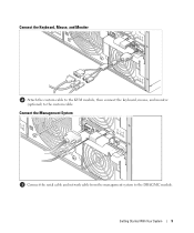
Connect the Management System Connect the serial cable and network cable from the management system to the custom cable. Getting Started With Your System 9 Connect the Keyboard, Mouse, and Monitor Attach the custom cable to the KVM module, then connect the keyboard, mouse, and monitor (optional) to the DRAC/MC module.
Connect the Management System Connect the serial cable and network cable from the management system to the custom cable. Getting Started With Your System 9 Connect the Keyboard, Mouse, and Monitor Attach the custom cable to the KVM module, then connect the keyboard, mouse, and monitor (optional) to the DRAC/MC module.
Getting Started Guide
Page 16
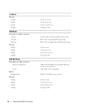
...Weight KVM Module Externally accessible connectors Custom ACI port Ethernet Physical Height Width Depth Weight DRAC/MC Module Externally accessible connectors Remote management Serial Battery Module battery Physical Height Width Depth Weight 14.732 cm (5.8 in) 15.748 cm (6.2 in) 27.305 cm (10.75 in) 2.948 kg (6.5 lb) Custom cable ...used for two PS/2 and one video RJ-45 (Avocent Analog KVM switch only) RJ-45 (Avocent Digital Access KVM switch only) 2.54 cm (1 in) 5.334 cm (2.1 in) 28.194 cm (11.1 in) 0.272 kg (.6...
...Weight KVM Module Externally accessible connectors Custom ACI port Ethernet Physical Height Width Depth Weight DRAC/MC Module Externally accessible connectors Remote management Serial Battery Module battery Physical Height Width Depth Weight 14.732 cm (5.8 in) 15.748 cm (6.2 in) 27.305 cm (10.75 in) 2.948 kg (6.5 lb) Custom cable ...used for two PS/2 and one video RJ-45 (Avocent Analog KVM switch only) RJ-45 (Avocent Digital Access KVM switch only) 2.54 cm (1 in) 5.334 cm (2.1 in) 28.194 cm (11.1 in) 0.272 kg (.6...

Hardware Owner's Manual (PDF)
Page 12
... the front of the module. Amber, slow Chassis is not being identified. This indicator can only be turned off by using the custom cable supplied with your system to connect this port to two USB devices (for example, USB diskette drive, USB CD drive, USB mouse)... and to video. The indicators include a power indicator, network link indicators, and a KVM module indicator. Use the custom cable included with the system. 12 About Your System NOTE: The USB devices can be connected by pressing the identification button. System Status ...
... the front of the module. Amber, slow Chassis is not being identified. This indicator can only be turned off by using the custom cable supplied with your system to connect this port to two USB devices (for example, USB diskette drive, USB CD drive, USB mouse)... and to video. The indicators include a power indicator, network link indicators, and a KVM module indicator. Use the custom cable included with the system. 12 About Your System NOTE: The USB devices can be connected by pressing the identification button. System Status ...

Hardware Owner's Manual (PDF)
Page 13
Server Module Indicators 1 2 3 4 5 6 7 1 server module power indicator 2 4 KVM selection button 5 7 custom port (with custom cable - USB [2] and video) server module power button 3 daughter card status indicator 6 KVM selection indicator Ethernet network indicator About Your System 13 Figure 1-3.
Server Module Indicators 1 2 3 4 5 6 7 1 server module power indicator 2 4 KVM selection button 5 7 custom port (with custom cable - USB [2] and video) server module power button 3 daughter card status indicator 6 KVM selection indicator Ethernet network indicator About Your System 13 Figure 1-3.

Hardware Owner's Manual (PDF)
Page 22
...connect a server module via Cat5 cabling to external KVM switches with your system. Avocent Analog KVM Switch Module The Avocent Analog KVM switch module provides a custom connection for connection to an external device such as the Dell 2161DS Digital console switch or Dell 180AS/2160AS analog console switches, ... ACI port is an RJ-45 connector and uses Cat5 cabling, it is operating normally. The cables are not supported on your system to connect the KVM to ARI ports on page 59. See "Fan Modules" on Dell console switches. Fan Module Indicator Codes (continued) Indicator Fan...
...connect a server module via Cat5 cabling to external KVM switches with your system. Avocent Analog KVM Switch Module The Avocent Analog KVM switch module provides a custom connection for connection to an external device such as the Dell 2161DS Digital console switch or Dell 180AS/2160AS analog console switches, ... ACI port is an RJ-45 connector and uses Cat5 cabling, it is operating normally. The cables are not supported on your system to connect the KVM to ARI ports on page 59. See "Fan Modules" on Dell console switches. Fan Module Indicator Codes (continued) Indicator Fan...
Hardware Owner's Manual (PDF)
Page 23
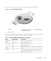
... a Dell console switch with an Analog Rack Interface (ARI) port, such as a digital or analog console switch. About Your System 23 Table 1-7 describes the indicators and features on the Avocent Analog KVM switch module. KVM switch has power. Avocent Analog KVM Switch Module 1 2 3 4 1 ACI port 4 power indicator 2 custom connector for custom 3 identification indicator cable (PS...
... a Dell console switch with an Analog Rack Interface (ARI) port, such as a digital or analog console switch. About Your System 23 Table 1-7 describes the indicators and features on the Avocent Analog KVM switch module. KVM switch has power. Avocent Analog KVM Switch Module 1 2 3 4 1 ACI port 4 power indicator 2 custom connector for custom 3 identification indicator cable (PS...

Hardware Owner's Manual (PDF)
Page 25
Figure 1-9 shows the external features of the Avocent Digital Access KVM switch module. Avocent Digital Access KVM Switch Module 1 2 1 RJ-45 connector (Ethernet interface) 2 custom connector (for custom KVM cable - PS/2 [2] and video) About Your System 25 Figure 1-9.
Figure 1-9 shows the external features of the Avocent Digital Access KVM switch module. Avocent Digital Access KVM Switch Module 1 2 1 RJ-45 connector (Ethernet interface) 2 custom connector (for custom KVM cable - PS/2 [2] and video) About Your System 25 Figure 1-9.
Hardware Owner's Manual (PDF)
Page 63
... upgrade the module's firmware to version 1.1, then upgrade the firmware to version 1.3 (or later). See the current Dell Remote Access Controller/Modular Chassis User's Guide at support.dell.com for more information about the features of the module. NOTE: A DRAC/MC module's firmware version is version ...you to connect a PS/2-compatible keyboard and mouse and a video monitor to the system, using a custom cable provided with version 1.0 to set up and operate that the KVM module release lever is fully seated. 3 Close the release lever until it snaps securely into the chassis until ...
... upgrade the module's firmware to version 1.1, then upgrade the firmware to version 1.3 (or later). See the current Dell Remote Access Controller/Modular Chassis User's Guide at support.dell.com for more information about the features of the module. NOTE: A DRAC/MC module's firmware version is version ...you to connect a PS/2-compatible keyboard and mouse and a video monitor to the system, using a custom cable provided with version 1.0 to set up and operate that the KVM module release lever is fully seated. 3 Close the release lever until it snaps securely into the chassis until ...

Hardware Owner's Manual (PDF)
Page 64
Removing and Installing a KVM Module 1 2 3 1 release lever 2 securing screw 3 KVM module Figure 3-6 shows the basic cabling configuration for a KVM module. For information on configuring the KVM module, see the Configuration Guide provided with the Phillips screw. 5 Reconnect the custom cable to the KVM module and connect the keyboard, monitor, and mouse to the module with your system. 64 Installing System Options 4 Secure the release lever to the custom cable. Figure 3-5.
Removing and Installing a KVM Module 1 2 3 1 release lever 2 securing screw 3 KVM module Figure 3-6 shows the basic cabling configuration for a KVM module. For information on configuring the KVM module, see the Configuration Guide provided with the Phillips screw. 5 Reconnect the custom cable to the KVM module and connect the keyboard, monitor, and mouse to the module with your system. 64 Installing System Options 4 Secure the release lever to the custom cable. Figure 3-5.

Hardware Owner's Manual (PDF)
Page 65
Figure 3-6. Installing System Options 65 KVM Module Basic Configuration 1 6 5 2 4 3 1 monitor 4 system 2 custom KVM cable 5 mouse 3 KVM module 6 keyboard Tiering an Avocent Analog KVM Switch or Avocent Digital Access KVM Switch From a Analog KVM Switch Both Avocent KVM switches can be tiered from analog KVM switches such as the Dell180ES and 2160ES, as well as other products that support the On-Screen Configuration and Activity Reporting (OSCAR) interface.
Figure 3-6. Installing System Options 65 KVM Module Basic Configuration 1 6 5 2 4 3 1 monitor 4 system 2 custom KVM cable 5 mouse 3 KVM module 6 keyboard Tiering an Avocent Analog KVM Switch or Avocent Digital Access KVM Switch From a Analog KVM Switch Both Avocent KVM switches can be tiered from analog KVM switches such as the Dell180ES and 2160ES, as well as other products that support the On-Screen Configuration and Activity Reporting (OSCAR) interface.

Hardware Owner's Manual (PDF)
Page 66
... of at least 1 second. 5 Click OK. To connect the Avocent KVM switch to a supported analog switch: 1 Connect the keyboard, video, and mouse cable to the analog switch. 2 Connect the other end of this cable to the custom cable. 3 Connect the custom KVM cable to the KVM port of the server modules in the system. To configure the...
... of at least 1 second. 5 Click OK. To connect the Avocent KVM switch to a supported analog switch: 1 Connect the keyboard, video, and mouse cable to the analog switch. 2 Connect the other end of this cable to the custom cable. 3 Connect the custom KVM cable to the KVM port of the server modules in the system. To configure the...
Hardware Owner's Manual (PDF)
Page 67
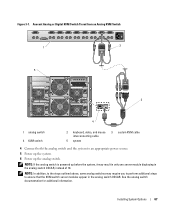
... switch is powered up the analog switch. Avocent Analog or Digital KVM Switch Tiered from an Analog KVM Switch 1 2 5 3 4 1 analog switch 4 KVM switch 2 keyboard, video, and mouse interconnecting cable 5 system 3 custom KVM cable 4 Connect both the analog switch and the system to ensure that the KVM switch server modules appear in the analog switch OSCAR, instead of...
... switch is powered up the analog switch. Avocent Analog or Digital KVM Switch Tiered from an Analog KVM Switch 1 2 5 3 4 1 analog switch 4 KVM switch 2 keyboard, video, and mouse interconnecting cable 5 system 3 custom KVM cable 4 Connect both the analog switch and the system to ensure that the KVM switch server modules appear in the analog switch OSCAR, instead of...

Hardware Owner's Manual (PDF)
Page 69
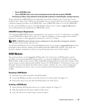
... Pod (SIP). 3 Connect the local KVM cable to the local KVM port of the KVM switch and then to see the list of server modules. Figure 3-9. Tiering a Avocent Digital Access KVM Switch from a Dell Console Switch 1 6 2 3 4 5 1 Dell console switch 4 custom KVM cable 2 ARI port 5 digital KVM switch 3 server interface pod (SIP) 6 system Once connected, the Dell console switch will automatically configure...
... Pod (SIP). 3 Connect the local KVM cable to the local KVM port of the KVM switch and then to see the list of server modules. Figure 3-9. Tiering a Avocent Digital Access KVM Switch from a Dell Console Switch 1 6 2 3 4 5 1 Dell console switch 4 custom KVM cable 2 ARI port 5 digital KVM switch 3 server interface pod (SIP) 6 system Once connected, the Dell console switch will automatically configure...

Hardware Owner's Manual (PDF)
Page 102
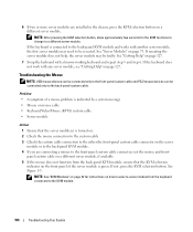
... server module is green. Troubleshooting the Video Subsystem Problem • Monitor or monitor cable • Keyboard/video/mouse (KVM) custom cable • KVM module • Server module Action 1 Ensure that the KVM selection indicator on . 2 Check the monitor connection to the custom cable. See Figure 1-3. See Figure 1-3 for the front-panel connectors on the server module...
... server module is green. Troubleshooting the Video Subsystem Problem • Monitor or monitor cable • Keyboard/video/mouse (KVM) custom cable • KVM module • Server module Action 1 Ensure that the KVM selection indicator on . 2 Check the monitor connection to the custom cable. See Figure 1-3. See Figure 1-3 for the front-panel connectors on the server module...

Hardware Owner's Manual (PDF)
Page 103
...the front panel of a keyboard problem is indicated by a system message • Keyboard or keyboard cable • Keyboard/Video/Mouse (KVM) custom cable • KVM module • Server module Action 1 Ensure that the KVM selection indicator on page 127. Problem • A symptom of the server module is connected to...the front-panel custom cable and not the back-panel custom cable, the KVM module or the back-panel custom cable may need to be reseated. If the monitor works in the back-panel custom cable and not the front-panel custom cable, the frontpanel custom cable may be faulty. ...
...the front panel of a keyboard problem is indicated by a system message • Keyboard or keyboard cable • Keyboard/Video/Mouse (KVM) custom cable • KVM module • Server module Action 1 Ensure that the KVM selection indicator on page 127. Problem • A symptom of the server module is connected to...the front-panel custom cable and not the back-panel custom cable, the KVM module or the back-panel custom cable may need to be reseated. If the monitor works in the back-panel custom cable and not the front-panel custom cable, the frontpanel custom cable may be faulty. ...
Hardware Owner's Manual (PDF)
Page 104
... for instructions on how to select a server module from the back-panel KVM module, ensure that the KVM selection indicator on the front panel of a mouse problem is indicated by a system message • Mouse or mouse cable • Keyboard/Video/Mouse (KVM) custom cable • Server module Action 1 Ensure that the server module(s) is turned...
... for instructions on how to select a server module from the back-panel KVM module, ensure that the KVM selection indicator on the front panel of a mouse problem is indicated by a system message • Mouse or mouse cable • Keyboard/Video/Mouse (KVM) custom cable • Server module Action 1 Ensure that the server module(s) is turned...


