McDATA 4416 Fibre Channel Switch Module
Page 3
...01 3 of the SilkWorm 4016, read this entire document before beginning. One green/amber LED to the PowerEdge 1855 documentation for details about the connection • One 10/100 Mbit/sec autosensing Ethernet port with an... Fibre Channel Ports" on page 11 • "Optional Software Features" on page 5 • "Inserting the SilkWorm 4016 into a Dell PowerEdge 1855 chassis and perform basic initial configuration. It provides the following features: • Up to six external autosensing (1, 2, and 4 ... page 4 • "Unpacking the SilkWorm 4016" on page 12 • "Where to the DRAC/MC;
...01 3 of the SilkWorm 4016, read this entire document before beginning. One green/amber LED to the PowerEdge 1855 documentation for details about the connection • One 10/100 Mbit/sec autosensing Ethernet port with an... Fibre Channel Ports" on page 11 • "Optional Software Features" on page 5 • "Inserting the SilkWorm 4016 into a Dell PowerEdge 1855 chassis and perform basic initial configuration. It provides the following features: • Up to six external autosensing (1, 2, and 4 ... page 4 • "Unpacking the SilkWorm 4016" on page 12 • "Where to the DRAC/MC;

McDATA 4416 Fibre Channel Switch Module
Page 4
One green power LED to indicate DRAC/MC status Each SilkWorm 4016 switch contains: • One PowerPC 405GP processor with a clock speed of these LEDs can be found in the SilkWorm 4016 ..., accessible at the front of the port side of the switch, is used to indicate system status - The insertion and removal arm is inserted into a PowerEdge 1855, as shown. The port side faces out when the switch is located just above the port side of 12 SilkWorm 4016 Quickstart Guide Publication...
One green power LED to indicate DRAC/MC status Each SilkWorm 4016 switch contains: • One PowerPC 405GP processor with a clock speed of these LEDs can be found in the SilkWorm 4016 ..., accessible at the front of the port side of the switch, is used to indicate system status - The insertion and removal arm is inserted into a PowerEdge 1855, as shown. The port side faces out when the switch is located just above the port side of 12 SilkWorm 4016 Quickstart Guide Publication...
McDATA 4416 Fibre Channel Switch Module
Page 5
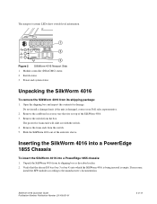
... from the box. The nonport (system) LEDs show switch-level information. 1 10 2 ! 3 Figure 2 SilkWorm 4016 Nonport Side 1 Module controller (DRAC/MC) status 2 Switch status 3 Power and system status Unpacking the SilkWorm 4016 To remove the SilkWorm 4016 from the switch. 5. Remove the foam ends... the SilkWorm 4016 into which the SilkWorm 4016 is being inserted is damaged, contact your Dell sales representative. 2. Remove the cardboard accessory tray that the chassis I/O bay (bay 3 or bay 4) into a PowerEdge 1855 chassis: 1. Do not install a damaged unit: if the unit is empty....
... from the box. The nonport (system) LEDs show switch-level information. 1 10 2 ! 3 Figure 2 SilkWorm 4016 Nonport Side 1 Module controller (DRAC/MC) status 2 Switch status 3 Power and system status Unpacking the SilkWorm 4016 To remove the SilkWorm 4016 from the switch. 5. Remove the foam ends... the SilkWorm 4016 into which the SilkWorm 4016 is being inserted is damaged, contact your Dell sales representative. 2. Remove the cardboard accessory tray that the chassis I/O bay (bay 3 or bay 4) into a PowerEdge 1855 chassis: 1. Do not install a damaged unit: if the unit is empty....

McDATA 4416 Fibre Channel Switch Module
Page 8
...Guide Publication Number: Publication Number: 53-100051-01 Use the DRAC/MC to the network until the IP address is activated, the switch runs self-diagnostic tests (such as POST). Refer to the Dell PowerEdge 1855 documentation for details about SFP modules. For instructions on how... subnet mask and gateway address • A serial cable to connect to the PowerEdge 1855 chassis • SFP transceivers and compatible fibre cables, as directed by the Dell PowerEdge 1855 documentation. The DRAC/MC creates a connection to the switch for backing up the switch configuration Caution ...
...Guide Publication Number: Publication Number: 53-100051-01 Use the DRAC/MC to the network until the IP address is activated, the switch runs self-diagnostic tests (such as POST). Refer to the Dell PowerEdge 1855 documentation for details about SFP modules. For instructions on how... subnet mask and gateway address • A serial cable to connect to the PowerEdge 1855 chassis • SFP transceivers and compatible fibre cables, as directed by the Dell PowerEdge 1855 documentation. The DRAC/MC creates a connection to the switch for backing up the switch configuration Caution ...

McDATA 4416 Fibre Channel Switch Module
Page 9
... domain ID is configured to a unique value. b. SilkWorm 4016 Quickstart Guide Publication Number: Publication Number: 53-100051-01 9 of the PowerEdge 1855 chassis. Create a serial connection to the switch as shown in use , the domain ID for details about setting up the terminal ... join the fabric. If the switch is automatically reset to 10.77.77.77. Refer to the PowerEdge 1855 documentation for the new switch is connected to the PowerEdge 1855 chassis DRAC/MC. 2. Modify the domain ID if required. a. The command prompts display sequentially; The SilkWorm 4016...
... domain ID is configured to a unique value. b. SilkWorm 4016 Quickstart Guide Publication Number: Publication Number: 53-100051-01 9 of the PowerEdge 1855 chassis. Create a serial connection to the switch as shown in use , the domain ID for details about setting up the terminal ... join the fabric. If the switch is automatically reset to 10.77.77.77. Refer to the PowerEdge 1855 documentation for the new switch is connected to the PowerEdge 1855 chassis DRAC/MC. 2. Modify the domain ID if required. a. The command prompts display sequentially; The SilkWorm 4016...

McDATA 4416 Fibre Channel Switch Module
Page 11
...are used for the chassis. Enter the IP address of 12 Each DRAC/MC has a serial connection to ensure correct orientation. Configuring the Fibre Channel Ports The DRAC/MC provides the control point for configuring and monitoring the installed switches.... These connections are described in detail in the address field. This command uploads the switch configuration to the server, making it available for downloading to ensure that it is available for downloading to the PowerEdge...
...are used for the chassis. Enter the IP address of 12 Each DRAC/MC has a serial connection to ensure correct orientation. Configuring the Fibre Channel Ports The DRAC/MC provides the control point for configuring and monitoring the installed switches.... These connections are described in detail in the address field. This command uploads the switch configuration to the server, making it available for downloading to ensure that it is available for downloading to the PowerEdge...
Configuration Guide
Page 5
... USB Drive, Keyboard, and Mouse to the Server Module Front Panel 10 Installing an Operating System 10 Configuring the DRAC/MC Module 11 DRAC/MC Module Features 11 DRAC/MC Configuration Interface Options 12 Web-Based Interface 13 Serial or Telnet Console Interface 14 Using a Serial or Telnet ...Console 17 Redirecting the DRAC/MC Serial Console to the Ethernet Switch Module 19 Updating the DRAC/MC Module Firmware 19 Integrating the System Into the Network 22 Updating the PowerConnect Switch Module Firmware ...
... USB Drive, Keyboard, and Mouse to the Server Module Front Panel 10 Installing an Operating System 10 Configuring the DRAC/MC Module 11 DRAC/MC Module Features 11 DRAC/MC Configuration Interface Options 12 Web-Based Interface 13 Serial or Telnet Console Interface 14 Using a Serial or Telnet ...Console 17 Redirecting the DRAC/MC Serial Console to the Ethernet Switch Module 19 Updating the DRAC/MC Module Firmware 19 Integrating the System Into the Network 22 Updating the PowerConnect Switch Module Firmware ...

Configuration Guide
Page 6
... the Avocent Digital Access KVM Module 43 Configuring the Avocent Digital Access KVM Module Using the DRAC/MC 43 Using the Video Viewer 44 Using Virtual Media 45 Updating the KVM Firmware 47 Using the DRAC/MC Web-based Interface to Update the KVM Firmware 47 Using the RACADM Command Line Interface...
... the Avocent Digital Access KVM Module 43 Configuring the Avocent Digital Access KVM Module Using the DRAC/MC 43 Using the Video Viewer 44 Using Virtual Media 45 Updating the KVM Firmware 47 Using the DRAC/MC Web-based Interface to Update the KVM Firmware 47 Using the RACADM Command Line Interface...
Configuration Guide
Page 7
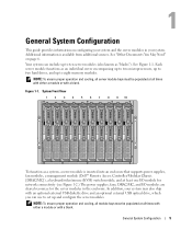
... server modules. See Figure 1-1. Additional information is inserted into an enclosure that supports power supplies, fan modules, a management module (Dell™ Remote Access Controller/Modular Chassis [DRAC/MC]), a keyboard/video/mouse (KVM) switch module, and at least one I/O module for network connectivity (see Figure 1-2.) The... power supplies, fans, DRAC/MC, and I/O modules are shared resources for the server modules in your system may also ship with a blank. General System ...
... server modules. See Figure 1-1. Additional information is inserted into an enclosure that supports power supplies, fan modules, a management module (Dell™ Remote Access Controller/Modular Chassis [DRAC/MC]), a keyboard/video/mouse (KVM) switch module, and at least one I/O module for network connectivity (see Figure 1-2.) The... power supplies, fans, DRAC/MC, and I/O modules are shared resources for the server modules in your system may also ship with a blank. General System ...

Configuration Guide
Page 8
... 6 3 7 2 1 8 1 I/O bay 2 4 I/O bay 1 7 KVM module 10 blanks (2) 9 2 fan modules (2) 5 Fibre Channel pass-through module 8 DRAC/MC module 11 I/O bay 4 3 Ethernet switch module 6 I/O bay 3 9 power supply modules (4) 12 blanks (2) Other Documents You May Need The Product Information Guide provides ...install or replace system components. • The Dell Remote Access Controller/Modular Chassis User's Guide provides detailed information on using the remote management features of the system. • The Dell PowerEdge Expandable RAID Controller 5iR Integrated Mirroring Guide describes ...
... 6 3 7 2 1 8 1 I/O bay 2 4 I/O bay 1 7 KVM module 10 blanks (2) 9 2 fan modules (2) 5 Fibre Channel pass-through module 8 DRAC/MC module 11 I/O bay 4 3 Ethernet switch module 6 I/O bay 3 9 power supply modules (4) 12 blanks (2) Other Documents You May Need The Product Information Guide provides ...install or replace system components. • The Dell Remote Access Controller/Modular Chassis User's Guide provides detailed information on using the remote management features of the system. • The Dell PowerEdge Expandable RAID Controller 5iR Integrated Mirroring Guide describes ...

Configuration Guide
Page 10
KVM Module Basic Configuration 1 6 5 2 4 3 1 monitor 4 DRAC/MC module 2 custom KVM cable 5 mouse 3 KVM module 6 keyboard 4 If required, configure the hard drives for RAID 1, the drives in your server module are already ... the BMC or to installation of the operating system. See "Serial or Telnet Console Interface" on page 9 for more information. Configure RAID 1 prior to the DRAC/MC module serial port in the server module System Setup program. NOTE: If you ordered your server module configured for RAID 1 or integrated mirroring. Figure...
KVM Module Basic Configuration 1 6 5 2 4 3 1 monitor 4 DRAC/MC module 2 custom KVM cable 5 mouse 3 KVM module 6 keyboard 4 If required, configure the hard drives for RAID 1, the drives in your server module are already ... the BMC or to installation of the operating system. See "Serial or Telnet Console Interface" on page 9 for more information. Configure RAID 1 prior to the DRAC/MC module serial port in the server module System Setup program. NOTE: If you ordered your server module configured for RAID 1 or integrated mirroring. Figure...
Configuration Guide
Page 11
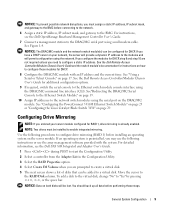
... server module. NOTICE: To prevent possible network disruptions, you must be added to the DRAC/MC serial port using the DRAC/MC command line interface (CLI). See the Dell Remote Access Controller/Modular Chassis User's Guide for RAID 1, drive mirroring is preinstalled, you... you configure the modules for DHCP. 8 Configure the DRAC/MC module with the system. For detailed information, see the Dell OpenManage Baseboard Management Controller User's Guide. 7 Connect a management station to a virtual disk. See the Dell Remote Access Controller/Modular Chassis User's Guide and the ...
... server module. NOTICE: To prevent possible network disruptions, you must be added to the DRAC/MC serial port using the DRAC/MC command line interface (CLI). See the Dell Remote Access Controller/Modular Chassis User's Guide for RAID 1, drive mirroring is preinstalled, you... you configure the modules for DHCP. 8 Configure the DRAC/MC module with the system. For detailed information, see the Dell OpenManage Baseboard Management Controller User's Guide. 7 Connect a management station to a virtual disk. See the Dell Remote Access Controller/Modular Chassis User's Guide and the ...

Configuration Guide
Page 13
... operation, both modules must have firmware version 1.3 or later. Configuring the DRAC/MC Module This section includes general configuration information for the DRAC/MC (see the Dell Remote Access Controller/Modular Chassis User's Guide. Mixing two DRAC/MC modules with firmware versions earlier than 1.3 may cause the enclosure to power down I/O modules in bays...
... operation, both modules must have firmware version 1.3 or later. Configuring the DRAC/MC Module This section includes general configuration information for the DRAC/MC (see the Dell Remote Access Controller/Modular Chassis User's Guide. Mixing two DRAC/MC modules with firmware versions earlier than 1.3 may cause the enclosure to power down I/O modules in bays...

Configuration Guide
Page 14
... LAN is in recovery mode or manufacturing mode. The DRAC/MC is linked. Fault indicator Serial connector Off Amber Amber blinking The DRAC/MC is not active. In a single (nonredundant) configuration, the DRAC/MC failed. Network interface controller activity indicator Primary/standby indicator...Interface" on page 14. 12 General System Configuration None Used for the primary DRAC/MC (redundant DRAC/MC configurations only) The DRAC/MC is not linked. Provides access to access the DRAC/MC using the following interfaces: • Web-based interface - Amber blinking...
... LAN is in recovery mode or manufacturing mode. The DRAC/MC is linked. Fault indicator Serial connector Off Amber Amber blinking The DRAC/MC is not active. In a single (nonredundant) configuration, the DRAC/MC failed. Network interface controller activity indicator Primary/standby indicator...Interface" on page 14. 12 General System Configuration None Used for the primary DRAC/MC (redundant DRAC/MC configurations only) The DRAC/MC is not linked. Provides access to access the DRAC/MC using the following interfaces: • Web-based interface - Amber blinking...

Configuration Guide
Page 15
...and the default password is the IP address for the DRAC/MC. To fix this option and restart Internet Explorer. NOTE: When you run multiple DRAC/MC sessions using the DRAC/MC interface, see the online help or the Dell Remote Access Controller/Modular Chassis User's Guide. Run ...the Mozilla Profile Manager from the operating system shell prompt by typing mozilla -profilemanager. Accessing the DRAC/MC Web-Based Interface 1 Open...
...and the default password is the IP address for the DRAC/MC. To fix this option and restart Internet Explorer. NOTE: When you run multiple DRAC/MC sessions using the DRAC/MC interface, see the online help or the Dell Remote Access Controller/Modular Chassis User's Guide. Run ...the Mozilla Profile Manager from the operating system shell prompt by typing mozilla -profilemanager. Accessing the DRAC/MC Web-Based Interface 1 Open...

Configuration Guide
Page 16
...down and select Integrated Devices. 4 Set the Integrated Devices options to the following settings: Remote Terminal Type - Serial or Telnet Console Interface The DRAC/MC supports a serial and Telnet interface for its command line interface (CLI) and has the capability to switch this interface to any server ...text displays properly, use an Xterm window to lose the selection. Once you have completed these steps, you can redirect the server console to the DRAC/MC remotely. 1 Turn on or restart your terminal is displayed again. 5 Press to VT200. Enabled NOTE: If your server module. 2 ...
...down and select Integrated Devices. 4 Set the Integrated Devices options to the following settings: Remote Terminal Type - Serial or Telnet Console Interface The DRAC/MC supports a serial and Telnet interface for its command line interface (CLI) and has the capability to switch this interface to any server ...text displays properly, use an Xterm window to lose the selection. Once you have completed these steps, you can redirect the server console to the DRAC/MC remotely. 1 Turn on or restart your terminal is displayed again. 5 Press to VT200. Enabled NOTE: If your server module. 2 ...

Configuration Guide
Page 17
..., type your console screen appropriately, use Hilgraeve's HyperTerminal Private Edition version 6.3. 1 Connect the null modem cable to the serial port on the DRAC/MC module and to the client system. 2 Click the Start button, point to Programs→ Accessories→ Communications, and then click HyperTerminal....: text box, select the COM port on using Minicom for serial text console redirection to configure the DRAC/MC BIOS, it may be useful to the DRAC/MC Using HyperTerminal for information on the management station (for Serial Console Emulation Setting Description Bits Per Second...
..., type your console screen appropriately, use Hilgraeve's HyperTerminal Private Edition version 6.3. 1 Connect the null modem cable to the serial port on the DRAC/MC module and to the client system. 2 Click the Start button, point to Programs→ Accessories→ Communications, and then click HyperTerminal....: text box, select the COM port on using Minicom for serial text console redirection to configure the DRAC/MC BIOS, it may be useful to the DRAC/MC Using HyperTerminal for information on the management station (for Serial Console Emulation Setting Description Bits Per Second...

Configuration Guide
Page 18
...the command prompt. 3 Resize the window to 80 x 25 prior to using Telnet. 4 To connect to configure the DRAC/MC using the RACADM CLI. For more information, see the Dell Remote Access Controller/Modular Chassis User's Guide. To enable Telnet, use either the Web-based user interface Configuration tab, or... for Telnet Console Redirection (Red Hat Enterprise Linux and SUSE Linux Enterprise Server) NOTE: When you are using the serial console. NOTE: The DRAC/MC default IP address is 192.168.0.120. 16 General System Configuration See "Using a Serial or Telnet Console" on page 17 for the ...
...the command prompt. 3 Resize the window to 80 x 25 prior to using Telnet. 4 To connect to configure the DRAC/MC using the RACADM CLI. For more information, see the Dell Remote Access Controller/Modular Chassis User's Guide. To enable Telnet, use either the Web-based user interface Configuration tab, or... for Telnet Console Redirection (Red Hat Enterprise Linux and SUSE Linux Enterprise Server) NOTE: When you are using the serial console. NOTE: The DRAC/MC default IP address is 192.168.0.120. 16 General System Configuration See "Using a Serial or Telnet Console" on page 17 for the ...

Configuration Guide
Page 19
... Telnet console. Using a Serial or Telnet Console NOTE: If you first enable Telnet in the Dell Remote Access Controller/Modular Chassis User's Guide. 1 Click OK. You can type serial commands or RACADM CLI commands in a DRAC/MC Telnet session, see the Microsoft Knowledge Base article 824810 on configuring the system enclosure using...
... Telnet console. Using a Serial or Telnet Console NOTE: If you first enable Telnet in the Dell Remote Access Controller/Modular Chassis User's Guide. 1 Click OK. You can type serial commands or RACADM CLI commands in a DRAC/MC Telnet session, see the Microsoft Knowledge Base article 824810 on configuring the system enclosure using...
Configuration Guide
Page 20
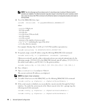
...enable the console remotely through the Telnet interface. NOTE: By default, Telnet is disabled. 8 To enable Telnet access to the DRAC/MC, use the following DRAC/MC CLI command: racadm setniccfg -s [ ] Obtain your network's specific address information from your network administrator. ss is the ...30:15 PM would be represented as: racadm setractime -d 20040525133015.000000-300 5 If required, assign a static IP address using the following DRAC/MC CLI command: racadm config -g cfgSerial -o cfgSerialTelnetEnable 1 9 If the serial console is the minute - The Ethernet switch may take ...
...enable the console remotely through the Telnet interface. NOTE: By default, Telnet is disabled. 8 To enable Telnet access to the DRAC/MC, use the following DRAC/MC CLI command: racadm setniccfg -s [ ] Obtain your network's specific address information from your network administrator. ss is the ...30:15 PM would be represented as: racadm setractime -d 20040525133015.000000-300 5 If required, assign a static IP address using the following DRAC/MC CLI command: racadm config -g cfgSerial -o cfgSerialTelnetEnable 1 9 If the serial console is the minute - The Ethernet switch may take ...


