Configuration Guide
Page 7
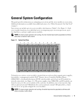
Each server module functions as an individual server encompassing up to two microprocessors, up to two hard drives, and up to ten server modules (also known as a system, a server module is available from additional sources. In addition, your system. General... either a module or with a blank. See Figure 1-1. Additional information is inserted into an enclosure that supports power supplies, fan modules, a management module (Dell™ Remote Access Controller/Modular Chassis [DRAC/MC]), a keyboard/video/mouse (KVM) switch module, and at all times with either a module or with a...
Each server module functions as an individual server encompassing up to two microprocessors, up to two hard drives, and up to ten server modules (also known as a system, a server module is available from additional sources. In addition, your system. General... either a module or with a blank. See Figure 1-1. Additional information is inserted into an enclosure that supports power supplies, fan modules, a management module (Dell™ Remote Access Controller/Modular Chassis [DRAC/MC]), a keyboard/video/mouse (KVM) switch module, and at all times with either a module or with a...

Configuration Guide
Page 10
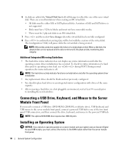
.... KVM Module Basic Configuration 1 6 5 2 4 3 1 monitor 4 DRAC/MC module 2 custom KVM cable 5 mouse 3 KVM module 6 keyboard 4 If required, configure the hard drives for RAID 1, the drives in the server module System Setup program. See "Configuring Drive Mirroring" on page 14. 8 General System Configuration See "Serial or Telnet Console Interface" on page 9 for more information. NOTE...
.... KVM Module Basic Configuration 1 6 5 2 4 3 1 monitor 4 DRAC/MC module 2 custom KVM cable 5 mouse 3 KVM module 6 keyboard 4 If required, configure the hard drives for RAID 1, the drives in the server module System Setup program. See "Configuring Drive Mirroring" on page 14. 8 General System Configuration See "Serial or Telnet Console Interface" on page 9 for more information. NOTE...
Configuration Guide
Page 12
...disk fails, the physical disk can be replaced and the data re-mirrored to reflect the size of the same capacity. • After removing a hard drive in an IM virtual disk. 7 Press and then select Save changes when the virtual disk has been fully configured. 8 Press to confirm that existing ...; Disks must have 512-byte blocks and must not have removable media. • There must connect the monitor to installing the new hard drive. Connecting a USB Drive, Keyboard, and Mouse to the Server Module Front Panel If you must be blank and not previously configured. • You should replace...
...disk fails, the physical disk can be replaced and the data re-mirrored to reflect the size of the same capacity. • After removing a hard drive in an IM virtual disk. 7 Press and then select Save changes when the virtual disk has been fully configured. 8 Press to confirm that existing ...; Disks must have 512-byte blocks and must not have removable media. • There must connect the monitor to installing the new hard drive. Connecting a USB Drive, Keyboard, and Mouse to the Server Module Front Panel If you must be blank and not previously configured. • You should replace...
Getting Started Guide
Page 6
...evaluating system components and devices. USB devices include a mouse, a keyboard, flash drive, a 1.44-MB, 3.5-inch diskette drive, or an optical drive. NOTE: Only Dell-supplied USB diskette drives and optical drives are supported; Maximum resolution is included with your solutions software documentation for up to ... that you use only a USB 2.0-compliant cable with a length not to two 2.5-inch, SAS or SATA hot-pluggable hard drives. • Support for more information Supported Operating Systems Your system supports the following operating systems: • Microsoft® Windows...
...evaluating system components and devices. USB devices include a mouse, a keyboard, flash drive, a 1.44-MB, 3.5-inch diskette drive, or an optical drive. NOTE: Only Dell-supplied USB diskette drives and optical drives are supported; Maximum resolution is included with your solutions software documentation for up to ... that you use only a USB 2.0-compliant cable with a length not to two 2.5-inch, SAS or SATA hot-pluggable hard drives. • Support for more information Supported Operating Systems Your system supports the following operating systems: • Microsoft® Windows...
Getting Started Guide
Page 14
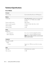
Technical Specifications Server Module Processor Processor type Memory Architecture Memory module sockets Memory module capacities Minimum RAM Maximum RAM Drives Hard Drives SAS configuration SATA configuration Connectors Externally accessible Front Custom Video Video type Video memory Up to two Intel Xeon Processor 5000 Sequence FBD DDR II... (when available) operation Eight 240-pin 256 MB, 512 MB, 1 GB, 2 GB, or 4 GB 512 MB 32 GB One or two 2.5-inch hot-pluggable hard drives One or two 2.5-inch hot-pluggable hard drives NOTE: SAS and SATA hard drives cannot be mixed within a server module.
Technical Specifications Server Module Processor Processor type Memory Architecture Memory module sockets Memory module capacities Minimum RAM Maximum RAM Drives Hard Drives SAS configuration SATA configuration Connectors Externally accessible Front Custom Video Video type Video memory Up to two Intel Xeon Processor 5000 Sequence FBD DDR II... (when available) operation Eight 240-pin 256 MB, 512 MB, 1 GB, 2 GB, or 4 GB 512 MB 32 GB One or two 2.5-inch hot-pluggable hard drives One or two 2.5-inch hot-pluggable hard drives NOTE: SAS and SATA hard drives cannot be mixed within a server module.
Hardware Owner's Manual (PDF)
Page 3
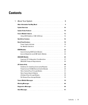
... Your System 9 Other Information You May Need 9 System Overview 10 System Status Features 10 Server Module Features 12 Using USB Diskette or USB CD Drives 16 Hard-Drive Features 16 Back-Panel Features 18 Power Supply Indicator 19 Fan Module Indicators 21 KVM Modules 22 Avocent Analog KVM Switch Module 22 Avocent Digital...
... Your System 9 Other Information You May Need 9 System Overview 10 System Status Features 10 Server Module Features 12 Using USB Diskette or USB CD Drives 16 Hard-Drive Features 16 Back-Panel Features 18 Power Supply Indicator 19 Fan Module Indicators 21 KVM Modules 22 Avocent Analog KVM Switch Module 22 Avocent Digital...

Hardware Owner's Manual (PDF)
Page 5
... KVM Switch From a Analog KVM Switch 65 Tiering an Avocent Analog KVM Switch From a Dell Console Switch . . . 68 Tiering an Avocent Digital Access KVM Switch From a Dell Console Switch 69 Chassis I/O Module 70 I/O Module Placements 71 Installing an I/O Module 72 ... 82 Activating the Integrated NIC TOE 84 Processors 84 Server Module Battery 88 Hard Drives 89 Removing a Hard Drive 90 Configuring the Boot Drive 91 Removing a Hard Drive From a Hard-Drive Carrier 91 Installing a Hard Drive Into a Drive Carrier 91 Back-Panel Module Cage Assembly (Service-Only Procedure 92 Removing the...
... KVM Switch From a Analog KVM Switch 65 Tiering an Avocent Analog KVM Switch From a Dell Console Switch . . . 68 Tiering an Avocent Digital Access KVM Switch From a Dell Console Switch 69 Chassis I/O Module 70 I/O Module Placements 71 Installing an I/O Module 72 ... 82 Activating the Integrated NIC TOE 84 Processors 84 Server Module Battery 88 Hard Drives 89 Removing a Hard Drive 90 Configuring the Boot Drive 91 Removing a Hard Drive From a Hard-Drive Carrier 91 Installing a Hard Drive Into a Drive Carrier 91 Back-Panel Module Cage Assembly (Service-Only Procedure 92 Removing the...

Hardware Owner's Manual (PDF)
Page 6
... DRAC/MC Module 109 Troubleshooting a Network Switch Module 110 Troubleshooting Server Module Components 110 Inside the Server Module 111 Troubleshooting Server Module Memory 112 Troubleshooting Hard Drives 113 Troubleshooting Microprocessors 114 Troubleshooting the Server Module Board 114 Troubleshooting the Server Module Battery 115 6 Contents
... DRAC/MC Module 109 Troubleshooting a Network Switch Module 110 Troubleshooting Server Module Components 110 Inside the Server Module 111 Troubleshooting Server Module Memory 112 Troubleshooting Hard Drives 113 Troubleshooting Microprocessors 114 Troubleshooting the Server Module Board 114 Troubleshooting the Server Module Battery 115 6 Contents
Hardware Owner's Manual (PDF)
Page 10
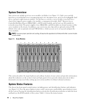
... (Dell™ Remote Access Controller/Modular Chassis [DRAC/MC]), a KVM switch module, and at all bays must be populated at least one I /O modules are shared resources of the system. To function as an individual server encompassing up to two microprocessors, up to two hot-pluggable hard drives, and... To ensure proper operation and cooling, all times with either a server module or with an optional external USB diskette drive and an optional external USB CD drive, which you may need when setting up and configure the server modules. press and hold the power button to obtain ...
... (Dell™ Remote Access Controller/Modular Chassis [DRAC/MC]), a KVM switch module, and at all bays must be populated at least one I /O modules are shared resources of the system. To function as an individual server encompassing up to two microprocessors, up to two hot-pluggable hard drives, and... To ensure proper operation and cooling, all times with either a server module or with an optional external USB diskette drive and an optional external USB CD drive, which you may need when setting up and configure the server modules. press and hold the power button to obtain ...
Hardware Owner's Manual (PDF)
Page 16
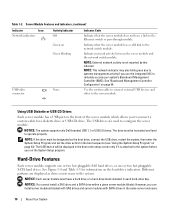
... Dell-branded USB 1.1 or USB 2.0 drives. NOTICE: Each server module must have a link to the system before you to operate properly. Table 1-2. The USB drives are displayed as first in the boot sequence (see "Using the System Setup Program" on the hard-drive indicators. The drive... switch module. See "Baseboard Management Controller Configuration" on Green blinking Indicates that the server module does not have a hard drive or a hard-drive blank installed in the same server enclosure. 16 About Your System Server Module Features and Indicators (continued) Indicator Icon ...
... Dell-branded USB 1.1 or USB 2.0 drives. NOTICE: Each server module must have a link to the system before you to operate properly. Table 1-2. The USB drives are displayed as first in the boot sequence (see "Using the System Setup Program" on the hard-drive indicators. The drive... switch module. See "Baseboard Management Controller Configuration" on Green blinking Indicates that the server module does not have a hard drive or a hard-drive blank installed in the same server enclosure. 16 About Your System Server Module Features and Indicators (continued) Indicator Icon ...

Hardware Owner's Manual (PDF)
Page 17
... Amber Amber blinking slowly, green blinking slowly, then off to the server module. Drive has failed or has an error. Drive is off Indicator Code • Drive is ready for RAID hard drive configurations. Hard-Drive Features and Indicators 1 2 1 drive activity indicator 2 drive status indicator NOTE: The hard-drive status indicator is active. About Your System 17 Figure 1-4. For non-RAID...
... Amber Amber blinking slowly, green blinking slowly, then off to the server module. Drive has failed or has an error. Drive is off Indicator Code • Drive is ready for RAID hard drive configurations. Hard-Drive Features and Indicators 1 2 1 drive activity indicator 2 drive status indicator NOTE: The hard-drive status indicator is active. About Your System 17 Figure 1-4. For non-RAID...

Hardware Owner's Manual (PDF)
Page 38
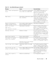
...Faulty server module board. keystroke POST to install Faulty or improperly installed. No boot device available Faulty or missing diskette drive, optical drive, or hard drive. See "Using the System Setup Program" on page 127. Memory odd/even logic failure at start address to end ...the System Setup program. Reseat the daughter card. Use a bootable diskette. See "I/O Module Daughter Card" on page 89. See "Hard Drives" on page 82. Server Module Messages (continued) Message Causes Corrective Actions Memory address line failure at address, read value expecting value ...
...Faulty server module board. keystroke POST to install Faulty or improperly installed. No boot device available Faulty or missing diskette drive, optical drive, or hard drive. See "Using the System Setup Program" on page 127. Memory odd/even logic failure at start address to end ...the System Setup program. Reseat the daughter card. Use a bootable diskette. See "I/O Module Daughter Card" on page 89. See "Hard Drives" on page 82. Server Module Messages (continued) Message Causes Corrective Actions Memory address line failure at address, read value expecting value ...
Hardware Owner's Manual (PDF)
Page 39
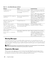
...Your System 39 See Figure 6-2 for a BIOS update. See "Troubleshooting USB Devices" on page 105 or "Troubleshooting Hard Drives" on page 127. Faulty diskette or hard drive. Incorrect Time or Date settings; and reboot the server module. See "Troubleshooting Server Module Memory" on page 127....have changed . If the problem persists, see "Getting Help" on page 43. custom cable is properly connected. Ensure that the drive, or hard drive. If the problem persists, see "Getting Help" on page 112. Ensure that all memory modules are properly installed. faulty Check...
...Your System 39 See Figure 6-2 for a BIOS update. See "Troubleshooting USB Devices" on page 105 or "Troubleshooting Hard Drives" on page 127. Faulty diskette or hard drive. Incorrect Time or Date settings; and reboot the server module. See "Troubleshooting Server Module Memory" on page 127....have changed . If the problem persists, see "Getting Help" on page 43. custom cable is properly connected. Ensure that the drive, or hard drive. If the problem persists, see "Getting Help" on page 112. Ensure that all memory modules are properly installed. faulty Check...
Hardware Owner's Manual (PDF)
Page 40
... See "General Memory Module error, but the memory configuration is not supported by Dell. Warning! No microcode update loaded for a BIOS update using the Dell Support website at support.dell.com. See "Troubleshooting USB Devices" on page 105 or "Troubleshooting Hard Drives" on page 78. Diagnostic error messages are installed. Table 1-13. Server Module Messages...
... See "General Memory Module error, but the memory configuration is not supported by Dell. Warning! No microcode update loaded for a BIOS update using the Dell Support website at support.dell.com. See "Troubleshooting USB Devices" on page 105 or "Troubleshooting Hard Drives" on page 78. Diagnostic error messages are installed. Table 1-13. Server Module Messages...
Hardware Owner's Manual (PDF)
Page 46
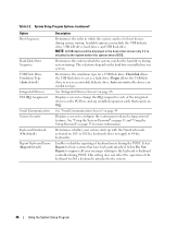
...NOTE: A USB device will be displayed in which the system searches the hard drives during system startup. Select Report for a USB flash drive. Displays a screen to change the IRQ assigned to act as a hard drive. Table 2-2. Auto automatically chooses an emulation type. See "Using the System... Available options can include the USB diskette drive, USB CD drive, hard drives, and USB flash drive. or 102-key keyboards (does not apply to configure the system password and setup password features. Hard disk allows the USB flash drive to the system. 46 Using the System...
...NOTE: A USB device will be displayed in which the system searches the hard drives during system startup. Select Report for a USB flash drive. Displays a screen to change the IRQ assigned to act as a hard drive. Table 2-2. Auto automatically chooses an emulation type. See "Using the System... Available options can include the USB diskette drive, USB CD drive, hard drives, and USB flash drive. or 102-key keyboards (does not apply to configure the system password and setup password features. Hard disk allows the USB flash drive to the system. 46 Using the System...

Hardware Owner's Manual (PDF)
Page 57
Hard drives • Back-panel module cage assembly (service-only procedure) • Chassis control panel assembly (service-only procedure) • Server module control panel assembly (service-only ... procedures in this section describe how to remove and install system components and server module components, including: • Power supply modules • Fan Modules • Dell Remote Access Controller/Modular Chassis (DRAC/MC) module • KVM modules • Network switch modules • Server modules • Server module components - TOE NIC - Memory...
Hard drives • Back-panel module cage assembly (service-only procedure) • Chassis control panel assembly (service-only procedure) • Server module control panel assembly (service-only ... procedures in this section describe how to remove and install system components and server module components, including: • Power supply modules • Fan Modules • Dell Remote Access Controller/Modular Chassis (DRAC/MC) module • KVM modules • Network switch modules • Server modules • Server module components - TOE NIC - Memory...
Hardware Owner's Manual (PDF)
Page 58
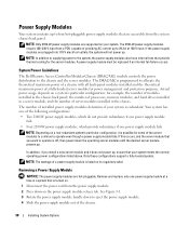
...8226; Four 2100-W power supply modules, which provide redundancy if one power supply module at 180 V input. System Power Guidelines The Dell Remote Access Controller/Modular Chassis (DRAC/MC) module controls the power distribution to eject the power supply module. 4 Slide the power ...power cord from the power supply module. 2 Press down to the chassis and the server modules. the number of processors, memory modules, and hard drives installed in a system that is listed on a system's particular configuration; Only those configurations support a fully-loaded system. NOTE: Only 2100-W ...
...8226; Four 2100-W power supply modules, which provide redundancy if one power supply module at 180 V input. System Power Guidelines The Dell Remote Access Controller/Modular Chassis (DRAC/MC) module controls the power distribution to eject the power supply module. 4 Slide the power ...power cord from the power supply module. 2 Press down to the chassis and the server modules. the number of processors, memory modules, and hard drives installed in a system that is listed on a system's particular configuration; Only those configurations support a fully-loaded system. NOTE: Only 2100-W ...

Hardware Owner's Manual (PDF)
Page 73
... handle Installing System Options 73 When a server module is off , its cable connections. Removing a Server Module 1 Ensure that must be attached to two processors, two hard drives, six memory modules, and one daughter card. NOTICE: If you are permanently removing the server module, install a server module blank. Operating the system for information...
... handle Installing System Options 73 When a server module is off , its cable connections. Removing a Server Module 1 Ensure that must be attached to two processors, two hard drives, six memory modules, and one daughter card. NOTICE: If you are permanently removing the server module, install a server module blank. Operating the system for information...

Hardware Owner's Manual (PDF)
Page 76
Inside a Server Module 1 2 6 5 3 4 1 optional daughter card 4 hard drive 0 2 memory modules 5 hard drive 1 3 heat sink and processor 2 6 heat sink and processor 1 Closing the Server Module CAUTION: Only trained service technicians are left inside the system. See your Product ...
Inside a Server Module 1 2 6 5 3 4 1 optional daughter card 4 hard drive 0 2 memory modules 5 hard drive 1 3 heat sink and processor 2 6 heat sink and processor 1 Closing the Server Module CAUTION: Only trained service technicians are left inside the system. See your Product ...

Hardware Owner's Manual (PDF)
Page 77
... to remove and install the following components: • Memory modules • Daughter cards • Integrated NIC TOE feature • Processors • Server module battery • Hard drives Memory You can purchase memory upgrade kits from Dell. NOTICE: Use only 533-MHz or 677-MHz (when available) DDR II FB memory modules. Figure 3-15.
... to remove and install the following components: • Memory modules • Daughter cards • Integrated NIC TOE feature • Processors • Server module battery • Hard drives Memory You can purchase memory upgrade kits from Dell. NOTICE: Use only 533-MHz or 677-MHz (when available) DDR II FB memory modules. Figure 3-15.


