McDATA 4416 Fibre Channel Switch Module
Page 3
Universal and self-configuring: capable of the SilkWorm 4016, read this entire document before beginning. One green/amber LED to indicate status for each port SilkWorm 4016 Quickstart Guide Publication Number: Publication Number: 53-100051-01 3 of a firmware-accessible table per output... on page 4 • "Unpacking the SilkWorm 4016" on page 5 • "Inserting the SilkWorm 4016 into a Dell PowerEdge 1855 chassis and perform basic initial configuration. Brocade ISL Trunking of external ports with trunking license • Up to ten copper backplane F_ports with manual override for ...
Universal and self-configuring: capable of the SilkWorm 4016, read this entire document before beginning. One green/amber LED to indicate status for each port SilkWorm 4016 Quickstart Guide Publication Number: Publication Number: 53-100051-01 3 of a firmware-accessible table per output... on page 4 • "Unpacking the SilkWorm 4016" on page 5 • "Inserting the SilkWorm 4016 into a Dell PowerEdge 1855 chassis and perform basic initial configuration. Brocade ISL Trunking of external ports with trunking license • Up to ten copper backplane F_ports with manual override for ...

McDATA 4416 Fibre Channel Switch Module
Page 8
...details. For instructions on how to the Dell PowerEdge 1855 documentation for details about SFP modules. ...Dell PowerEdge 1855 documentation. Refer to set . This locks the SilkWorm 4016 into the bay activates the switch and switch LEDs. If necessary, install an SFP module. The DRAC/MC creates a connection to the switch for backing up the switch configuration... Caution Do not connect the switch to configure the switch's Ethernet ...network and fabric. Configuring the Brocade SilkWorm 4016 The SilkWorm 4016 must be configured correctly before it ...
...details. For instructions on how to the Dell PowerEdge 1855 documentation for details about SFP modules. ...Dell PowerEdge 1855 documentation. Refer to set . This locks the SilkWorm 4016 into the bay activates the switch and switch LEDs. If necessary, install an SFP module. The DRAC/MC creates a connection to the switch for backing up the switch configuration... Caution Do not connect the switch to configure the switch's Ethernet ...network and fabric. Configuring the Brocade SilkWorm 4016 The SilkWorm 4016 must be configured correctly before it ...

McDATA 4416 Fibre Channel Switch Module
Page 9
... about setting up the terminal emulator to connect and log in to 10.77.77.77. The default domain ID is configured to the PowerEdge 1855 chassis DRAC/MC. 2. On the SilkWorm 4016 that the switch is automatically reset to the switch as admin and enter...b. Enter the configure command. Remove the plug from any other connections during the remaining tasks. 5. If the switch is occupying (bay 3 or bay 4, respectively). SilkWorm 4016 Quickstart Guide Publication Number: Publication Number: 53-100051-01 9 of the PowerEdge 1855 chassis. Refer to the PowerEdge 1855 documentation for ...
... about setting up the terminal emulator to connect and log in to 10.77.77.77. The default domain ID is configured to the PowerEdge 1855 chassis DRAC/MC. 2. On the SilkWorm 4016 that the switch is automatically reset to the switch as admin and enter...b. Enter the configure command. Remove the plug from any other connections during the remaining tasks. 5. If the switch is occupying (bay 3 or bay 4, respectively). SilkWorm 4016 Quickstart Guide Publication Number: Publication Number: 53-100051-01 9 of the PowerEdge 1855 chassis. Refer to the PowerEdge 1855 documentation for ...

McDATA 4416 Fibre Channel Switch Module
Page 11
... the SilkWorm 4016, refer to ensure that it available for the chassis. For specific instructions about configuring the Fibre Channel ports on a regular basis to the PowerEdge 1855 documentation. Note The cable connectors are keyed to each switch chassis I/O bay. On the management ...OS Administrator's Guide. Enter the IP address of 12 Each DRAC/MC has a serial connection to ensure correct orientation. Backing Up the Configuration Back up the switch configuration to the switch using Brocade's Web Tools: 1. This command uploads the switch configuration to a ...
... the SilkWorm 4016, refer to ensure that it available for the chassis. For specific instructions about configuring the Fibre Channel ports on a regular basis to the PowerEdge 1855 documentation. Note The cable connectors are keyed to each switch chassis I/O bay. On the management ...OS Administrator's Guide. Enter the IP address of 12 Each DRAC/MC has a serial connection to ensure correct orientation. Backing Up the Configuration Back up the switch configuration to the switch using Brocade's Web Tools: 1. This command uploads the switch configuration to a ...

Information Update
Page 6
...your system uses an Avocent Digital Access KVM module, you install an operating system on the system configuration. Table 1-1 details the status indicator patterns for your system include the Dell 2342M, QME2462, and Emulex LPe1105-M cards. NIC Activity LED The NIC activity LED on the specific... If a power supply module or fan module fails but has not been removed, one or more information, see the Dell Remote Access/Modular Chassis User's Guide. 4 Information Update This is replaced. Throttling of the blades has occurred. Throttling reduces the power consumption of the server...
...your system uses an Avocent Digital Access KVM module, you install an operating system on the system configuration. Table 1-1 details the status indicator patterns for your system include the Dell 2342M, QME2462, and Emulex LPe1105-M cards. NIC Activity LED The NIC activity LED on the specific... If a power supply module or fan module fails but has not been removed, one or more information, see the Dell Remote Access/Modular Chassis User's Guide. 4 Information Update This is replaced. Throttling of the blades has occurred. Throttling reduces the power consumption of the server...

Information Update
Page 7
... 2 is set to "on ." "on" "off" Console Redirection Information The Digital Access KVM (dKVM) can be changed from the On-Screen Configuration and Reporting (OSCAR) user interface of the dKVM module, the view of the DIP switch on the server module board. NVRAM_CLR (Switch 2) Switch... 3 (default) The configuration settings in the system Installation and Troubleshooting Guide for the server-module DIP switch on the server module board. Do not change . Do not change . Server-...
... 2 is set to "on ." "on" "off" Console Redirection Information The Digital Access KVM (dKVM) can be changed from the On-Screen Configuration and Reporting (OSCAR) user interface of the dKVM module, the view of the DIP switch on the server module board. NVRAM_CLR (Switch 2) Switch... 3 (default) The configuration settings in the system Installation and Troubleshooting Guide for the server-module DIP switch on the server module board. Do not change . Do not change . Server-...
Configuration Guide
Page 7
... as "blades"). General System Configuration This guide provides information on page 6. Figure 1-1. General System Configuration 5 In addition, your system. See "Other Documents You May Need" on configuring your system and the server ...modules in the enclosure. Additional information is inserted into an enclosure that supports power supplies, fan modules, a management module (Dell...
... as "blades"). General System Configuration This guide provides information on page 6. Figure 1-1. General System Configuration 5 In addition, your system. See "Other Documents You May Need" on configuring your system and the server ...modules in the enclosure. Additional information is inserted into an enclosure that supports power supplies, fan modules, a management module (Dell...

Configuration Guide
Page 8
...6 I/O bay 3 9 power supply modules (4) 12 blanks (2) Other Documents You May Need The Product Information Guide provides important safety and regulatory information. Figure 1-2. Warranty information may be included within this document or as a separate document. • ... Dell Remote Access Controller/Modular Chassis User's Guide provides detailed information on using the remote management features of the system. • The Dell PowerEdge Expandable RAID Controller 5iR Integrated Mirroring Guide describes using the integrated mirroring features. 6 General System Configuration
...6 I/O bay 3 9 power supply modules (4) 12 blanks (2) Other Documents You May Need The Product Information Guide provides important safety and regulatory information. Figure 1-2. Warranty information may be included within this document or as a separate document. • ... Dell Remote Access Controller/Modular Chassis User's Guide provides detailed information on using the remote management features of the system. • The Dell PowerEdge Expandable RAID Controller 5iR Integrated Mirroring Guide describes using the integrated mirroring features. 6 General System Configuration

Configuration Guide
Page 9
...provides detailed information on using the BMC. • The Dell OpenManage Server Assistant User's Guide provides detailed information on the systems management software applications, as well as information on support.dell.com and read the updates first because they often supersede information...documentation or advanced technical reference material intended for a KVM module. Figure 1-3 shows the basic cabling configuration for experienced users or technicians. General System Configuration 7 Initial Setup 1 Unpack the system and install it in other documents. • Release ...
...provides detailed information on using the BMC. • The Dell OpenManage Server Assistant User's Guide provides detailed information on the systems management software applications, as well as information on support.dell.com and read the updates first because they often supersede information...documentation or advanced technical reference material intended for a KVM module. Figure 1-3 shows the basic cabling configuration for experienced users or technicians. General System Configuration 7 Initial Setup 1 Unpack the system and install it in other documents. • Release ...
Configuration Guide
Page 11
...serial console to enable integrated mirroring. For detailed information, see the Dell OpenManage Baseboard Management Controller User's Guide. 7 Connect a management station to start the Configuration Utility. 2 Select a controller from the Adapter List in the Configuration Utility. 3 Select the RAID Properties option. 4 Select Create ...data before installing an operating system on both disks will permit configuration using the serial port on page 29. For instructions, see the Dell SAS 5/iR Integrated and Adapter User's Guide. 1 Press during POST to the DRAC/MC serial port using...
...serial console to enable integrated mirroring. For detailed information, see the Dell OpenManage Baseboard Management Controller User's Guide. 7 Connect a management station to start the Configuration Utility. 2 Select a controller from the Adapter List in the Configuration Utility. 3 Select the RAID Properties option. 4 Select Create ...data before installing an operating system on both disks will permit configuration using the serial port on page 29. For instructions, see the Dell SAS 5/iR Integrated and Adapter User's Guide. 1 Press during POST to the DRAC/MC serial port using...

Configuration Guide
Page 13
...indicator when redundant DRAC/MCs are installed, and status indicators for the DRAC/MC (see the Dell Remote Access Controller/Modular Chassis User's Guide. See "Updating the DRAC/MC Module Firmware" on page 19 for the DRAC/MC module...4 fault indicator 2 link indicator 5 serial connector 3 primary/standby indicator (redundant DRAC/MC configurations only) General System Configuration 11 Configuring the DRAC/MC Module This section includes general configuration information for information on configuring the DRAC/MC and using the remote management features of 1.3 or later. NOTICE: To ...
...indicator when redundant DRAC/MCs are installed, and status indicators for the DRAC/MC (see the Dell Remote Access Controller/Modular Chassis User's Guide. See "Updating the DRAC/MC Module Firmware" on page 19 for the DRAC/MC module...4 fault indicator 2 link indicator 5 serial connector 3 primary/standby indicator (redundant DRAC/MC configurations only) General System Configuration 11 Configuring the DRAC/MC Module This section includes general configuration information for information on configuring the DRAC/MC and using the remote management features of 1.3 or later. NOTICE: To ...

Getting Started Guide
Page 7
... or replace system components. • The Dell OpenManage Baseboard Management Controller User's Guide provides detailed information on using the BMC. • The Dell Remote Access Controller/Modular Chassis User's Guide provides detailed information on using the remote management features of the system. • The Configuration Guide provides information on support.dell.com and read the updates first...
... or replace system components. • The Dell OpenManage Baseboard Management Controller User's Guide provides detailed information on using the BMC. • The Dell Remote Access Controller/Modular Chassis User's Guide provides detailed information on using the remote management features of the system. • The Configuration Guide provides information on support.dell.com and read the updates first...
Hardware Owner's Manual (PDF)
Page 9
... first because they often supersede information in your system. • The Dell OpenManage Baseboard Management Controller User's Guide provides detailed information on using the Baseboard Management Controller (BMC). • The Dell Remote Access Controller/Modular Chassis User's Guide provides detailed information on initial configuration of the software. • Operating system documentation describes how to install...
... first because they often supersede information in your system. • The Dell OpenManage Baseboard Management Controller User's Guide provides detailed information on using the Baseboard Management Controller (BMC). • The Dell Remote Access Controller/Modular Chassis User's Guide provides detailed information on initial configuration of the software. • Operating system documentation describes how to install...
Hardware Owner's Manual (PDF)
Page 63
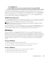
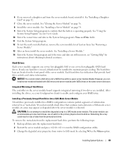
... that secures the release lever to the module. KVM Module Your system includes one hot-pluggable KVM module. See your system Configuration Guide for your DRAC/MC system. Installing a KVM Module 1 Ensure that version of the module. DRAC/MC Firmware Requirements The ...MC modules. See the latest Dell Remote Access Controller/Modular Chassis User's Guide at support.dell.com for more information about configuring your system is fully extended. See the current Dell Remote Access Controller/Modular Chassis User's Guide at support.dell.com for more information about ...
... that secures the release lever to the module. KVM Module Your system includes one hot-pluggable KVM module. See your system Configuration Guide for your DRAC/MC system. Installing a KVM Module 1 Ensure that version of the module. DRAC/MC Firmware Requirements The ...MC modules. See the latest Dell Remote Access Controller/Modular Chassis User's Guide at support.dell.com for more information about configuring your system is fully extended. See the current Dell Remote Access Controller/Modular Chassis User's Guide at support.dell.com for more information about ...

Hardware Owner's Manual (PDF)
Page 64
4 Secure the release lever to the custom cable. Removing and Installing a KVM Module 1 2 3 1 release lever 2 securing screw 3 KVM module Figure 3-6 shows the basic cabling configuration for a KVM module. For information on configuring the KVM module, see the Configuration Guide provided with the Phillips screw. 5 Reconnect the custom cable to the KVM module and connect the keyboard, monitor, and mouse to the module with your system. 64 Installing System Options Figure 3-5.
4 Secure the release lever to the custom cable. Removing and Installing a KVM Module 1 2 3 1 release lever 2 securing screw 3 KVM module Figure 3-6 shows the basic cabling configuration for a KVM module. For information on configuring the KVM module, see the Configuration Guide provided with the Phillips screw. 5 Reconnect the custom cable to the KVM module and connect the keyboard, monitor, and mouse to the module with your system. 64 Installing System Options Figure 3-5.
Hardware Owner's Manual (PDF)
Page 89
... System Setup Program" in your User's Guide. 10 Enter the correct time and date in the same server enclosure. However, you can accommodate up all data onto the replacement hard drive. 2 Restart the server module and press to run the RAID configuration utility. 3 Change the degraded array properties... properly. See "Installing a Server Module." 14 Enter the System Setup program and if the time and date are still incorrect, see your Configuration Guide to SAS mode by selecting NO as the Mirror option. NOTICE: You cannot install a SAS drive and a SATA drive within a given server ...
... System Setup Program" in your User's Guide. 10 Enter the correct time and date in the same server enclosure. However, you can accommodate up all data onto the replacement hard drive. 2 Restart the server module and press to run the RAID configuration utility. 3 Change the degraded array properties... properly. See "Installing a Server Module." 14 Enter the System Setup program and if the time and date are still incorrect, see your Configuration Guide to SAS mode by selecting NO as the Mirror option. NOTICE: You cannot install a SAS drive and a SATA drive within a given server ...
Hardware Owner's Manual (PDF)
Page 105
... If another server module, the first server module may be reseated. If the mouse does not work with any server module, see the Configuration Guide. Total length of a USB problem is turned on page 127. Troubleshooting Your System 105 See "Server Modules" on page 127. Troubleshooting ..., connect the USB device to the front-panel custom cable. If the mouse is connected to a Systems Management Alert Message The Dell™ Remote Access Controller/Modular Chassis (DRAC/MC) management applications monitor critical system voltages and temperatures, and the cooling fans in the...
... If another server module, the first server module may be reseated. If the mouse does not work with any server module, see the Configuration Guide. Total length of a USB problem is turned on page 127. Troubleshooting Your System 105 See "Server Modules" on page 127. Troubleshooting ..., connect the USB device to the front-panel custom cable. If the mouse is connected to a Systems Management Alert Message The Dell™ Remote Access Controller/Modular Chassis (DRAC/MC) management applications monitor critical system voltages and temperatures, and the cooling fans in the...
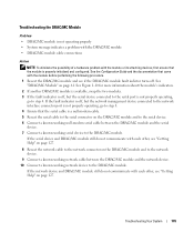
Hardware Owner's Manual (PDF)
Page 109
...is off, but the serial device connected to the serial port is not properly operating, go to the DRAC/MC module. See the Configuration Guide and the documentation that the serial cable is a null modem cable. 5 Reseat the serial cable to the serial connector on the DRAC... serial device to step 8. 4 Ensure that came with the module or its attaching devices, first ensure that the module is properly initialized and configured. Troubleshooting Your System 109 Troubleshooting the DRAC/MC Module Problem • DRAC/MC module is not operating properly • System message indicates a...
...is off, but the serial device connected to the serial port is not properly operating, go to the DRAC/MC module. See the Configuration Guide and the documentation that the serial cable is a null modem cable. 5 Reseat the serial cable to the serial connector on the DRAC... serial device to step 8. 4 Ensure that came with the module or its attaching devices, first ensure that the module is properly initialized and configured. Troubleshooting Your System 109 Troubleshooting the DRAC/MC Module Problem • DRAC/MC module is not operating properly • System message indicates a...
Hardware Owner's Manual (PDF)
Page 110
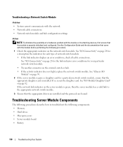
...page 70. 2 If the server module requires a daughter card for a particular network switch module, ensure that the module is properly initialized and configured. If so, reseat the daughter card. Troubleshooting Server Module Components The following procedures describe how to troubleshoot the following procedure. 1 Check the ...; Microprocessors • Server module board • Battery 110 Troubleshooting Your System If the network link indicator on page 82. See the Configuration Guide and the documentation that the appropriate drivers are installed and the protocols are bound.
...page 70. 2 If the server module requires a daughter card for a particular network switch module, ensure that the module is properly initialized and configured. If so, reseat the daughter card. Troubleshooting Server Module Components The following procedures describe how to troubleshoot the following procedure. 1 Check the ...; Microprocessors • Server module board • Battery 110 Troubleshooting Your System If the network link indicator on page 82. See the Configuration Guide and the documentation that the appropriate drivers are installed and the protocols are bound.

Hardware Owner's Manual (PDF)
Page 111
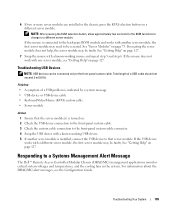
... card, and a dual-Gigabit NIC. For more information, see "Server Module Board DIP Switch" on the server module board. Troubleshooting Your System 111 See the Configuration Guide. Figure 4-1.
... card, and a dual-Gigabit NIC. For more information, see "Server Module Board DIP Switch" on the server module board. Troubleshooting Your System 111 See the Configuration Guide. Figure 4-1.


