
Information Update
Page 6
...USB Memory Key The PowerEdge 1950 III system provides an internal USB connector located on page 22. 6 Information Update The USB memory key can be enabled in the Integrated Devices screen of supporting 10-Mbps, 100-Mbps, and 1000-Mbps data rates and iSCSI remote boot. • Support ...1-1). See "Integrated Devices Screen" on the system board for use the internal USB connector, the Internal USB Port option must be used as a boot device, security key, or mass storage device. New Security Features • Trusted Program Module (TPM) support for improved security. • Optional ...
...USB Memory Key The PowerEdge 1950 III system provides an internal USB connector located on page 22. 6 Information Update The USB memory key can be enabled in the Integrated Devices screen of supporting 10-Mbps, 100-Mbps, and 1000-Mbps data rates and iSCSI remote boot. • Support ...1-1). See "Integrated Devices Screen" on the system board for use the internal USB connector, the Internal USB Port option must be used as a boot device, security key, or mass storage device. New Security Features • Trusted Program Module (TPM) support for improved security. • Optional ...
Information Update
Page 7
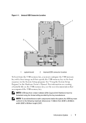
...thick (0.46") x 24.89mm width (0.98") x 66.8mm length (2.63"). Internal USB Connector Location 1 2 1 system board 2 internal USB connector location To boot from the USB memory key, you must be formatted using the format utility provided by the key manufacturer. NOTE: To avoid interference with... a boot image and then specify the USB memory key in the boot sequence in the Hardware Owner's Manual. See "Using the System Setup Program" in the System Setup program. Figure ...
...thick (0.46") x 24.89mm width (0.98") x 66.8mm length (2.63"). Internal USB Connector Location 1 2 1 system board 2 internal USB connector location To boot from the USB memory key, you must be formatted using the format utility provided by the key manufacturer. NOTE: To avoid interference with... a boot image and then specify the USB memory key in the boot sequence in the Hardware Owner's Manual. See "Using the System Setup Program" in the System Setup program. Figure ...
Information Update
Page 11
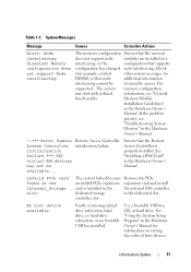
... 11 System Messages Message Causes Corrective Actions Alert! Check (for example, a failed other system messages for information on setting the order of boot devices. Memory Module Installation Guidelines" in the Internal_Storage slot! Invalid PCIe card found in the Hardware Owner's Manual. No... boot device available Faulty or missing optical drive subsystem, hard drive, or hard-drive subsystem, or no bootable USB key installed. See "...
... 11 System Messages Message Causes Corrective Actions Alert! Check (for example, a failed other system messages for information on setting the order of boot devices. Memory Module Installation Guidelines" in the Internal_Storage slot! Invalid PCIe card found in the Hardware Owner's Manual. No... boot device available Faulty or missing optical drive subsystem, hard drive, or hard-drive subsystem, or no bootable USB key installed. See "...
Information Update
Page 14
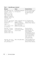
... update loaded See "Getting Help" in the Hardware Owner's Manual. Configuration change and reset the system. Press I to Ignore or M to Modify to continue system boot. A fatal system error occurred and caused the system to modify the TPM setting and restart. Press M to restart. pairs, as indicated by the n1 and...
... update loaded See "Getting Help" in the Hardware Owner's Manual. Configuration change and reset the system. Press I to Ignore or M to Modify to continue system boot. A fatal system error occurred and caused the system to modify the TPM setting and restart. Press M to restart. pairs, as indicated by the n1 and...
Information Update
Page 21
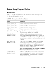
... the amount of video memory. Table 1-3. Redundant memory feature is disabled if the Node Interleaving field is set to Disabled, the memory runs at system boot. NOTE: The Node Interleaving field must be set to conserve energy.
... the amount of video memory. Table 1-3. Redundant memory feature is disabled if the Node Interleaving field is set to Disabled, the memory runs at system boot. NOTE: The Node Interleaving field must be set to conserve energy.
Information Update
Page 23
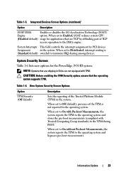
...to Distributed, interrupt routing is not reported to the DMA engine. System Interrupts This field controls the interrupt assignment for the PowerEdge 1950 III system. Information Update 23 CAUTION: Before enabling the TPM Security option, ensure that are shipping in China are not equipped...of the Trusted Platform Module (TPM) in the system. When set to On with Pre-boot Measurements, the system reports the TPM to the operating system and stores the pre-boot measurements (compliant with TPM. New System Security Screen Options Option TPM Security (Off default) ...
...to Distributed, interrupt routing is not reported to the DMA engine. System Interrupts This field controls the interrupt assignment for the PowerEdge 1950 III system. Information Update 23 CAUTION: Before enabling the TPM Security option, ensure that are shipping in China are not equipped...of the Trusted Platform Module (TPM) in the system. When set to On with Pre-boot Measurements, the system reports the TPM to the operating system and stores the pre-boot measurements (compliant with TPM. New System Security Screen Options Option TPM Security (Off default) ...

Information Update
Page 24
... (No default) Description Changes the operational state of the TPM are preserved). When set to Activate, the TPM is set to Off. Table 1-7. This prevents booting to enabling this option. Table 1-6.
... (No default) Description Changes the operational state of the TPM are preserved). When set to Activate, the TPM is set to Off. Table 1-7. This prevents booting to enabling this option. Table 1-6.
Information Update
Page 37
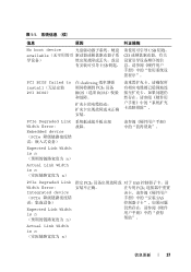
表 1-1 信息 原因 纠正措施 No boot device USB 钥匙、 available CD 导设备) USB PCI BIOS failed to install PCI BIOS) 在 shadowing PCIe 设备 ...
表 1-1 信息 原因 纠正措施 No boot device USB 钥匙、 available CD 导设备) USB PCI BIOS failed to install PCI BIOS) 在 shadowing PCIe 设备 ...
Information Update
Page 135
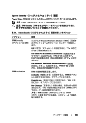
System Security PowerEdge 1950 III 1-6 TPM TPM Security(TPM OS が TPM 表 1-6. System Security 説明 TPM Security Trusted Platform Module(TPM Off ます。 Off TPM OS On with Pre-boot Measurements TPM が OS POST TCG TPM On without Pre-boot Measurements TPM が OS TPM Activation TPM Activate TPM Deactivate TPM No Change TPM TPM TPM Security(TPM Off 135
System Security PowerEdge 1950 III 1-6 TPM TPM Security(TPM OS が TPM 表 1-6. System Security 説明 TPM Security Trusted Platform Module(TPM Off ます。 Off TPM OS On with Pre-boot Measurements TPM が OS POST TCG TPM On without Pre-boot Measurements TPM が OS TPM Activation TPM Activate TPM Deactivate TPM No Change TPM TPM TPM Security(TPM Off 135
Information Update
Page 149
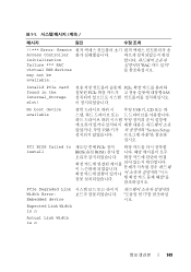
... n 149 표 1-1 메시지 원인 !!*** Error: Remote Access Controller initialization failure *** RAC virtual USB devices may not be available... PCIe PCIe SAS No boot device available USB 키, CD 또는 하 USB System Setup 십시오.
... n 149 표 1-1 메시지 원인 !!*** Error: Remote Access Controller initialization failure *** RAC virtual USB devices may not be available... PCIe PCIe SAS No boot device available USB 키, CD 또는 하 USB System Setup 십시오.
Information Update
Page 160
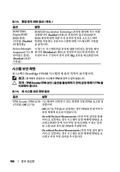
표 1-5 옵션 설명 I/OAT DMA Engine(I/OAT DMA Disabled I/OAT(I/O Acceleration Technology Enabled I/OAT가 DMA TCP TCP CPU System Interrupts PCI Assignment Distributed IRQ Standard 표 1-6에는 PowerEdge 1950 III TPM TPM Security (TPM TPM 표 1-6 옵션 설명 TPM Security (TPM TPM (기본값: Off (끄기)) Off TPM On with Pre-boot Measurements TPM POST TPM On without Pre-boot Measurements TPM 160
표 1-5 옵션 설명 I/OAT DMA Engine(I/OAT DMA Disabled I/OAT(I/O Acceleration Technology Enabled I/OAT가 DMA TCP TCP CPU System Interrupts PCI Assignment Distributed IRQ Standard 표 1-6에는 PowerEdge 1950 III TPM TPM Security (TPM TPM 표 1-6 옵션 설명 TPM Security (TPM TPM (기본값: Off (끄기)) Off TPM On with Pre-boot Measurements TPM POST TPM On without Pre-boot Measurements TPM 160

Hardware Owner's Manual (PDF)
Page 5
Expansion Cards 61 Installing an Expansion Card 61 Removing an Expansion Card 62 Configuring the Boot Device 63 Configuring the Boot Drive 63 System Memory 63 General Memory Module Installation Guidelines 64 Non-Optimal Memory Configurations 64 Memory Sparing Support 64 Memory Mirroring Support 65 Installing ...
Expansion Cards 61 Installing an Expansion Card 61 Removing an Expansion Card 62 Configuring the Boot Device 63 Configuring the Boot Drive 63 System Memory 63 General Memory Module Installation Guidelines 64 Non-Optimal Memory Configurations 64 Memory Sparing Support 64 Memory Mirroring Support 65 Installing ...
Hardware Owner's Manual (PDF)
Page 10
...User's Guide for more information, see the documentation for your system and try again. See your integrated NIC. If you to finish booting, and then restart your RAID card. Table 1-1. Enters the Baseboard Management Controller (BMC) Management Utility, which allows you have PXE ...system or documentation or advanced technical reference material intended for experienced users or technicians. See "Running the System Diagnostics" on support.dell.com and read the updates first because they often supersede information in other documents. • Release notes or readme files may...
...User's Guide for more information, see the documentation for your system and try again. See your integrated NIC. If you to finish booting, and then restart your RAID card. Table 1-1. Enters the Baseboard Management Controller (BMC) Management Utility, which allows you have PXE ...system or documentation or advanced technical reference material intended for experienced users or technicians. See "Running the System Diagnostics" on support.dell.com and read the updates first because they often supersede information in other documents. • Release notes or readme files may...
Hardware Owner's Manual (PDF)
Page 17
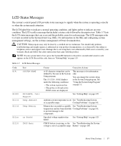
... troubleshooting and simple repairs as directed by the online or telephone service and support team. Damage due to servicing that is not authorized by Dell is not covered by descriptive text. Table 1-7. Specified voltage regulator has failed. For information on the SEL and configuring system management settings, ...see "Getting Help" on page 125. Read and follow the safety instructions that includes a status code followed by your system fails to boot, press the System ID button for at least five seconds until an error code appears on page 100. This message is powered on page...
... troubleshooting and simple repairs as directed by the online or telephone service and support team. Damage due to servicing that is not authorized by Dell is not covered by descriptive text. Table 1-7. Specified voltage regulator has failed. For information on the SEL and configuring system management settings, ...see "Getting Help" on page 125. Read and follow the safety instructions that includes a status code followed by your system fails to boot, press the System ID button for at least five seconds until an error code appears on page 100. This message is powered on page...
Hardware Owner's Manual (PDF)
Page 27
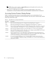
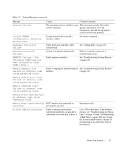
...Getting Help" on setting the order of manufacturing mode. on page 104. No boot device available Faulty or missing optical drive subsystem, hard drive, or hard-drive subsystem, or no boot disk in manufacturing mode. Invalid NVRAM configuration, Resource Re-allocated System detected and ...General failure The operating system is usually followed by out the command. Note the information, and take the system out of boot devices. Keyboard Controller failure Faulty keyboard controller; Reboot to take the appropriate action to carry This message is unable to resolve...
...Getting Help" on setting the order of manufacturing mode. on page 104. No boot device available Faulty or missing optical drive subsystem, hard drive, or hard-drive subsystem, or no boot disk in manufacturing mode. Invalid NVRAM configuration, Resource Re-allocated System detected and ...General failure The operating system is usually followed by out the command. Note the information, and take the system out of boot devices. Keyboard Controller failure Faulty keyboard controller; Reboot to take the appropriate action to carry This message is unable to resolve...
Hardware Owner's Manual (PDF)
Page 28
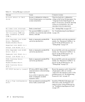
... or improperly installed PCIe card in the specified slot number. Plug & Play Configuration Error encountered in the specified slot. Table 1-8. System Messages (continued) Message No boot sector on page 107. 28 About Your System See your hard drive. PCIe Degraded Link Width Error: Embedded Bus#nn/Dev#nn/Funcn Faulty or...
... or improperly installed PCIe card in the specified slot number. Plug & Play Configuration Error encountered in the specified slot. Table 1-8. System Messages (continued) Message No boot sector on page 107. 28 About Your System See your hard drive. PCIe Degraded Link Width Error: Embedded Bus#nn/Dev#nn/Funcn Faulty or...
Hardware Owner's Manual (PDF)
Page 30
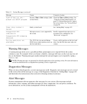
... For more information, see the documentation that came with your system. Alert Messages Systems management software generates alert messages for your the boot hard drive. Alert messages include information, status, warning, and failure messages for obtaining technical assistance. For example, before the system ...on the diskette. If the problem persists, replace the system battery. The key was pressed during Create a utility partition on the boot hard POST, but no ). Warning messages usually interrupt the task and require you to respond before you format a diskette, a ...
... For more information, see the documentation that came with your system. Alert Messages Systems management software generates alert messages for your the boot hard drive. Alert messages include information, status, warning, and failure messages for obtaining technical assistance. For example, before the system ...on the diskette. If the problem persists, replace the system battery. The key was pressed during Create a utility partition on the boot hard POST, but no ). Warning messages usually interrupt the task and require you to respond before you format a diskette, a ...

Hardware Owner's Manual (PDF)
Page 31
... your operating system. Record the information for correcting errors. 2 Using the System Setup Program After you press , allow the system to finish booting, and then restart your system and try again. If an error message appears while the system is normal for your system to send a ... hardware • Set or change information on page 25 for an explanation of the message. NOTE: After installing a memory upgrade, it is booting, make a note of the message and suggestions for future reference. Responding to Error Messages You can use to view or change user-selectable options...
... your operating system. Record the information for correcting errors. 2 Using the System Setup Program After you press , allow the system to finish booting, and then restart your system and try again. If an error message appears while the system is normal for your system to send a ... hardware • Set or change information on page 25 for an explanation of the message. NOTE: After installing a memory upgrade, it is booting, make a note of the message and suggestions for future reference. Responding to Error Messages You can use to view or change user-selectable options...
Hardware Owner's Manual (PDF)
Page 34
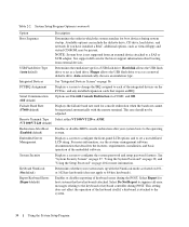
See support.dell.com for console redirection when the baud rate cannot be negotiated automatically ...as a hard drive. Failsafe Baud Rate (57600 default) Displays the failsafe baud rate used for the latest support information about booting from an external device attached to set a user-defined LCD string. See "System Security Screen" on page 37, "Using... Remote Terminal Type Select either VT 100/VT 220 or ANSI. (VT 100/VT 220 default) Redirection After Boot (Enabled default) Enables or disables BIOS console redirection after your system starts up with Console Redirection via COM2, and...
See support.dell.com for console redirection when the baud rate cannot be negotiated automatically ...as a hard drive. Failsafe Baud Rate (57600 default) Displays the failsafe baud rate used for the latest support information about booting from an external device attached to set a user-defined LCD string. See "System Security Screen" on page 37, "Using... Remote Terminal Type Select either VT 100/VT 220 or ANSI. (VT 100/VT 220 default) Redirection After Boot (Enabled default) Enables or disables BIOS console redirection after your system starts up with Console Redirection via COM2, and...
Hardware Owner's Manual (PDF)
Page 36
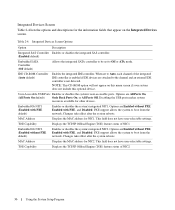
...) Allows the integrated SATA controller to be set to the channel and an external IDE controller is not detected. PXE support allows the system to boot from the network. NOTE: This CD-ROM option will not appear on the Integrated Devices screen. Options are attached to Auto, each channel of the... 2-4. TOE Capability Displays the TCP/IP Offload Engine (TOE) feature status of NIC2. 36 Using the System Setup Program PXE support allows the system to boot from the network.
...) Allows the integrated SATA controller to be set to the channel and an external IDE controller is not detected. PXE support allows the system to boot from the network. NOTE: This CD-ROM option will not appear on the Integrated Devices screen. Options are attached to Auto, each channel of the... 2-4. TOE Capability Displays the TCP/IP Offload Engine (TOE) feature status of NIC2. 36 Using the System Setup Program PXE support allows the system to boot from the network.


