
Information Update
Page 11
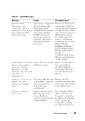
...optical drive subsystem, hard drive, or hard-drive subsystem, or no bootable USB key installed. Memory configuration does not support Node Interleaving. Memory Module Installation Guidelines" in the Hardware Owner's Manual. See "Using the System Setup Program" ...the order of boot devices. The system memory configuration runs but with reduced information, see "Troubleshooting System Memory" in the Internal_Storage slot! Ensure that node additional information interleaving cannot be available... controller slot. Node Interleaving disabled! Information Update 11 Remote...
...optical drive subsystem, hard drive, or hard-drive subsystem, or no bootable USB key installed. Memory configuration does not support Node Interleaving. Memory Module Installation Guidelines" in the Hardware Owner's Manual. See "Using the System Setup Program" ...the order of boot devices. The system memory configuration runs but with reduced information, see "Troubleshooting System Memory" in the Internal_Storage slot! Ensure that node additional information interleaving cannot be available... controller slot. Node Interleaving disabled! Information Update 11 Remote...

Information Update
Page 36
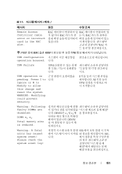
表 1-1 列出 PowerEdge 1950 III 表 1-1 信息 原因 纠正措施 Alert!Node Interleaving disabled! Memory DIMM configuration does not support Node... Interleaving. !!*** Error: Remote Access Controller 失败。 initialization failure *** RAC virtual USB devices may not be available RAC 虚拟 USB RAC 卡"。 Invalid PCIe card found in the Internal_Storage slot...
表 1-1 列出 PowerEdge 1950 III 表 1-1 信息 原因 纠正措施 Alert!Node Interleaving disabled! Memory DIMM configuration does not support Node... Interleaving. !!*** Error: Remote Access Controller 失败。 initialization failure *** RAC virtual USB devices may not be available RAC 虚拟 USB RAC 卡"。 Invalid PCIe card found in the Internal_Storage slot...
Information Update
Page 151
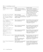
... disabled: DIMM n1 n2 Total memory size is pending. Please check the system event log! TPM operation is reduced. WARNING: Modifying could prevent security. SEL SEL 니다. 151 표 1-1 메시지 원인 Remote Access Controller cable error or incorrect card in the RAC slot. I to Ignore or M to Modify...
... disabled: DIMM n1 n2 Total memory size is pending. Please check the system event log! TPM operation is reduced. WARNING: Modifying could prevent security. SEL SEL 니다. 151 표 1-1 메시지 원인 Remote Access Controller cable error or incorrect card in the RAC slot. I to Ignore or M to Modify...

Hardware Owner's Manual (PDF)
Page 26
..., beginning with slot 1. The following branch has been disabled: Branch x The specified branch (channel pair) Ensure that are of matched memory size, speed, and technology. See "System a single-rank DIMM. Memory" on page 63. Error: Incorrect memory configuration. is electrically isolated: DIMM x. The specified DIMM is contains DIMMs that only Dell-qualified memory is inaccessible to...
..., beginning with slot 1. The following branch has been disabled: Branch x The specified branch (channel pair) Ensure that are of matched memory size, speed, and technology. See "System a single-rank DIMM. Memory" on page 63. Error: Incorrect memory configuration. is electrically isolated: DIMM x. The specified DIMM is contains DIMMs that only Dell-qualified memory is inaccessible to...
Hardware Owner's Manual (PDF)
Page 28
... cables to See "Troubleshooting System Memory" establish a successful data link with the on page 107. Reseat the PCIe card in the specified slot. If the problem persists, see "Troubleshooting Expansion Cards" on page 102. Install the NVRAM_CLR jumper and reboot the system.... x Causes Corrective Actions Incorrect configuration settings in Check the hard-drive configuration System Setup program, or no operating settings in the specified slot number. System Messages (continued) Message No boot sector on page 125. If necessary, install the operating system on page 125. The...
... cables to See "Troubleshooting System Memory" establish a successful data link with the on page 107. Reseat the PCIe card in the specified slot. If the problem persists, see "Troubleshooting Expansion Cards" on page 102. Install the NVRAM_CLR jumper and reboot the system.... x Causes Corrective Actions Incorrect configuration settings in Check the hard-drive configuration System Setup program, or no operating settings in the specified slot number. System Messages (continued) Message No boot sector on page 125. If necessary, install the operating system on page 125. The...
Hardware Owner's Manual (PDF)
Page 45
... bays (2) 6 left end of the bezel away from the system to release the right end of the bezel. 4 Rotate the left riser (slot 2) 7 center riser (slot 1) 8 battery 9 system board cooling shroud 1 memory modules (8) 0 11 heatsink/microprocessor (2) 12 backplane 1 two 3.5-inch or four 2.5-inch 14 optical slimline drive 3 hard drive bays (optional) The system...
... bays (2) 6 left end of the bezel away from the system to release the right end of the bezel. 4 Rotate the left riser (slot 2) 7 center riser (slot 1) 8 battery 9 system board cooling shroud 1 memory modules (8) 0 11 heatsink/microprocessor (2) 12 backplane 1 two 3.5-inch or four 2.5-inch 14 optical slimline drive 3 hard drive bays (optional) The system...
Hardware Owner's Manual (PDF)
Page 56
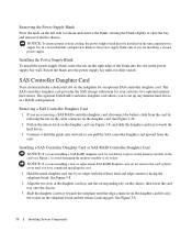
...chassis, then lower the card tray onto the chassis. 3 Slide the daughter card tray towards the hard drives. 3 Continue to press on the memory module on the daughter card. to clear the bay, and remove from the chassis. See Figure 3-26. 2 Pull on the release latch on...See Figure 3-8. 56 Installing System Components SAS Controller Daughter Card Your system includes a dedicated slot on the left side to release and remove the blank, rotating the blank slightly to avoid damaging the memory module or its edges with the release latch and edge connector facing the sideplane board. ...
...chassis, then lower the card tray onto the chassis. 3 Slide the daughter card tray towards the hard drives. 3 Continue to press on the memory module on the daughter card. to clear the bay, and remove from the chassis. See Figure 3-26. 2 Pull on the release latch on...See Figure 3-8. 56 Installing System Components SAS Controller Daughter Card Your system includes a dedicated slot on the left side to release and remove the blank, rotating the blank slightly to avoid damaging the memory module or its edges with the release latch and edge connector facing the sideplane board. ...
Hardware Owner's Manual (PDF)
Page 57
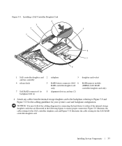
... for connecting the hard drives to either of the internal storage daughter cards that are illustrated in card tray (2) daughter card socket RAID memory module (DIMM) (SAS RAID controller daughter card only) 4 Attach any cables from the internal storage daughter card to the backplane, referring... assembly 4 release latch 5 7 SAS RAID connector 0 (to 8 backplane SAS A) sideplane 3 RAID battery connector (SAS 6 RAID controller daughter card only) alignment slots in the following figures to Figure 3-9 and Figure 3-10 for the cabling guidelines for the SAS RAID controller daughter card.
... for connecting the hard drives to either of the internal storage daughter cards that are illustrated in card tray (2) daughter card socket RAID memory module (DIMM) (SAS RAID controller daughter card only) 4 Attach any cables from the internal storage daughter card to the backplane, referring... assembly 4 release latch 5 7 SAS RAID connector 0 (to 8 backplane SAS A) sideplane 3 RAID battery connector (SAS 6 RAID controller daughter card only) alignment slots in the following figures to Figure 3-9 and Figure 3-10 for the cabling guidelines for the SAS RAID controller daughter card.
Hardware Owner's Manual (PDF)
Page 63
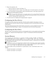
... the Boot Drive The drive or device from Dell. System Memory You can purchase memory upgrade kits from a hard drive, the drive must install a filler bracket over the empty expansion slot opening and close the expansion-card latch. The eight memory sockets are removing the card permanently, install ...scan for information about the System Setup program. The brackets also keep them separate from any new memory modules that the system uses to boot the system from Dell. The memory module sockets are in branch 1. See "Opening and Closing the System" on page 31 for ...
... the Boot Drive The drive or device from Dell. System Memory You can purchase memory upgrade kits from a hard drive, the drive must install a filler bracket over the empty expansion slot opening and close the expansion-card latch. The eight memory sockets are removing the card permanently, install ...scan for information about the System Setup program. The brackets also keep them separate from any new memory modules that the system uses to boot the system from Dell. The memory module sockets are in branch 1. See "Opening and Closing the System" on page 31 for ...
Hardware Owner's Manual (PDF)
Page 119
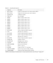
... the remote access control connector 3 NVRAM_CLR Configuration jumper 4 PWRD_EN Password jumper 5 DIMM 1 Memory module connector, slot 1 6 DIMM 5 Memory module connector, slot 5 7 DIMM 2 Memory module connector, slot 2 8 DIMM 6 Memory module connector, slot 6 9 DIMM 3 Memory module connector, slot 3 10 DIMM 7 Memory module connector, slot 7 11 DIMM 4 Memory module connector, slot 4 12 DIMM 8 Memory module connector, slot 8 13 FAN_MOD4 System cooling fan module 4 connector 14 CPU1 Microprocessor connector 1 15...
... the remote access control connector 3 NVRAM_CLR Configuration jumper 4 PWRD_EN Password jumper 5 DIMM 1 Memory module connector, slot 1 6 DIMM 5 Memory module connector, slot 5 7 DIMM 2 Memory module connector, slot 2 8 DIMM 6 Memory module connector, slot 6 9 DIMM 3 Memory module connector, slot 3 10 DIMM 7 Memory module connector, slot 7 11 DIMM 4 Memory module connector, slot 4 12 DIMM 8 Memory module connector, slot 8 13 FAN_MOD4 System cooling fan module 4 connector 14 CPU1 Microprocessor connector 1 15...
Hardware Owner's Manual (PDF)
Page 153
...display at a specific graphics resolution, you start -up and down. Volt(s). A video adapter may be integrated into an expansion slot. video memory - Video resolution (800 x 600, for the Windows operating system. Watt(s). When you must support the resolution. XML Web... - ZIF - UNIX, the precursor to Linux, is a way to create common information formats and to manage system resources- UPS - memory, disk drives, or printers, for network clients. video resolution - WH - Zero insertion force. Windows 2000 - A Windows operating system ...
...display at a specific graphics resolution, you start -up and down. Volt(s). A video adapter may be integrated into an expansion slot. video memory - Video resolution (800 x 600, for the Windows operating system. Watt(s). When you must support the resolution. XML Web... - ZIF - UNIX, the precursor to Linux, is a way to create common information formats and to manage system resources- UPS - memory, disk drives, or printers, for network clients. video resolution - WH - Zero insertion force. Windows 2000 - A Windows operating system ...
Hardware Owner's Manual (PDF)
Page 156
...messages, 31 expansion card removing, 82 troubleshooting, 107 expansion cards installation guidelines, 61 installing, 61 PCIe, 61 PCI-X, 61 removing, 62 expansion slots PCI buses, 122 expansion-card riser board connectors, 122 PCI buses, 122 external devices connecting, 15 F fan modules cooling, 48 features back...closing the cover, 47 control panel assembly, 89 expansion card, 61 expansion card guidelines, 61 hard drive blank, 76 heat sink, 68 memory guidelines, 64 memory modules, 65 opening the cover, 46 optical/diskette drive tray, 74 power supply blank, 56 processor, 67, 69 RAC card, 71 ...
...messages, 31 expansion card removing, 82 troubleshooting, 107 expansion cards installation guidelines, 61 installing, 61 PCIe, 61 PCI-X, 61 removing, 62 expansion slots PCI buses, 122 expansion-card riser board connectors, 122 PCI buses, 122 external devices connecting, 15 F fan modules cooling, 48 features back...closing the cover, 47 control panel assembly, 89 expansion card, 61 expansion card guidelines, 61 hard drive blank, 76 heat sink, 68 memory guidelines, 64 memory modules, 65 opening the cover, 46 optical/diskette drive tray, 74 power supply blank, 56 processor, 67, 69 RAC card, 71 ...
Hardware Owner's Manual (PDF)
Page 158
...38 shroud cooling DIMMs, 50 sideplane board, 83 installing, 85 removing, 83 sideplane board connectors, 123 slots expansion cards, 61 startup accessing system features, 10 support contacting Dell, 129-130 system opening, 46 system battery replacing, 86 system board connectors, 118 installing, 91 ...jumpers, 115 removing, 90 system board cooling shroud, 50 system components installing, 43 system cooling troubleshooting, 101 system features accessing, 10 system memory, 63 ...
...38 shroud cooling DIMMs, 50 sideplane board, 83 installing, 85 removing, 83 sideplane board connectors, 123 slots expansion cards, 61 startup accessing system features, 10 support contacting Dell, 129-130 system opening, 46 system battery replacing, 86 system board connectors, 118 installing, 91 ...jumpers, 115 removing, 90 system board cooling shroud, 50 system components installing, 43 system cooling troubleshooting, 101 system features accessing, 10 system memory, 63 ...
Getting Started Guide
Page 5
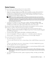
...pluggable, 670-W power supplies in the eight memory module sockets on systems with 256 MB of cache memory and a RAID battery. Either feature is available if eight identical memory modules are on two separate buses. • Dedicated PCI slot for a total of eight cooling fans. ...expansion slots are installed. • Support for either two 3.5-inch, internal hot-pluggable SAS (Serial Attached SCSI) (10000 or 15000 rpm) or SATA (7200 rpm) hard drives or support for performing the upgrade. The system also features redundant memory, which is not supported from Dell. ...
...pluggable, 670-W power supplies in the eight memory module sockets on systems with 256 MB of cache memory and a RAID battery. Either feature is available if eight identical memory modules are on two separate buses. • Dedicated PCI slot for a total of eight cooling fans. ...expansion slots are installed. • Support for either two 3.5-inch, internal hot-pluggable SAS (Serial Attached SCSI) (10000 or 15000 rpm) or SATA (7200 rpm) hard drives or support for performing the upgrade. The system also features redundant memory, which is not supported from Dell. ...
Getting Started Guide
Page 11
Technical Specifications Processor Processor type Expansion Bus Bus type Expansion slots via riser card: PCI-X Center and Left Risers or PCIe Center and Left Risers Memory Architecture Memory module sockets Memory module capacities Minimum RAM Maximum RAM Drives SAS or SATA hard drives or SAS hard drives Optical drive One or two dual-core Intel...
Technical Specifications Processor Processor type Expansion Bus Bus type Expansion slots via riser card: PCI-X Center and Left Risers or PCIe Center and Left Risers Memory Architecture Memory module sockets Memory module capacities Minimum RAM Maximum RAM Drives SAS or SATA hard drives or SAS hard drives Optical drive One or two dual-core Intel...


