

Installing a SATA Optical Drive
Page 9
... system to power and turn on the system board. See Figure 1-5. - See Figure 1-5. - For a PowerEdge 1900 system, connect to the CD/TBU connector on the system backplane. For a PowerEdge 1900, use the SATA_B connector. - See "Replacing the Center Fan Bracket" in the optical drive kit and...provided in your Hardware Owner's Manual. 10 Close the system. For a PowerEdge 2900 system, connect to an available power supply cable. 5 Replace the center fan bracket. For a PowerEdge 2900, use the SATA_D connector. PowerEdge 2900 and 1900 1 If the mounting screws are not attached to the...
... system to power and turn on the system board. See Figure 1-5. - See Figure 1-5. - For a PowerEdge 1900 system, connect to the CD/TBU connector on the system backplane. For a PowerEdge 1900, use the SATA_B connector. - See "Replacing the Center Fan Bracket" in the optical drive kit and...provided in your Hardware Owner's Manual. 10 Close the system. For a PowerEdge 2900 system, connect to an available power supply cable. 5 Replace the center fan bracket. For a PowerEdge 2900, use the SATA_D connector. PowerEdge 2900 and 1900 1 If the mounting screws are not attached to the...

Installing a SATA Optical Drive
Page 10
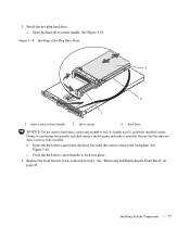
See "Closing the System" in a PowerEdge 2900 or 1900 3 2 4 5 1 1 optical drive 3 SATA data cable 5 SATA power connector on SAS backplane (PowerEdge 2900 only) 2 SATA power cable 4 SATA connector on the system and attached peripherals. 10 Installing a SATA Optical Drive SATA Cable Routing in your Hardware Owner's Manual. 10 Reconnect the system to power and turn on system board 8 Reconnect the cables to the SAS controller daughter card. 9 Close the system. Figure 1-5.
See "Closing the System" in a PowerEdge 2900 or 1900 3 2 4 5 1 1 optical drive 3 SATA data cable 5 SATA power connector on SAS backplane (PowerEdge 2900 only) 2 SATA power cable 4 SATA connector on the system and attached peripherals. 10 Installing a SATA Optical Drive SATA Cable Routing in your Hardware Owner's Manual. 10 Reconnect the system to power and turn on system board 8 Reconnect the cables to the SAS controller daughter card. 9 Close the system. Figure 1-5.
Hardware Owner's Manual (PDF)
Page 6
Expansion-Card Riser 82 Removing an Expansion-Card Riser 82 Installing an Expansion-Card Riser 83 Backplane Board 83 Removing the Backplane Board 83 Installing the Backplane Board 85 Sideplane Board 85 Removing the Sideplane Board 85 Installing the Sideplane Board 86 System Battery 86 Replacing the System Battery 86 Control Panel ...
Expansion-Card Riser 82 Removing an Expansion-Card Riser 82 Installing an Expansion-Card Riser 83 Backplane Board 83 Removing the Backplane Board 83 Installing the Backplane Board 85 Sideplane Board 85 Removing the Sideplane Board 85 Installing the Sideplane Board 86 System Battery 86 Replacing the System Battery 86 Control Panel ...
Hardware Owner's Manual (PDF)
Page 7
... Diagnostics Options 113 Viewing Information and Results 113 6 Jumpers and Connectors System Board Jumpers 115 Disabling a Forgotten Password 117 System Board Connectors 118 SAS/SATA Backplane Board Connectors 120 Expansion-Card Riser-Board Components and PCI Buses 122 SAS Sideplane Board Connectors 123 Contents 7
... Diagnostics Options 113 Viewing Information and Results 113 6 Jumpers and Connectors System Board Jumpers 115 Disabling a Forgotten Password 117 System Board Connectors 118 SAS/SATA Backplane Board Connectors 120 Expansion-Card Riser-Board Components and PCI Buses 122 SAS Sideplane Board Connectors 123 Contents 7
Hardware Owner's Manual (PDF)
Page 12
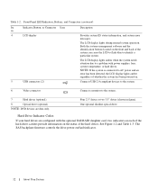
... has been detected, the LCD display lights amber regardless of whether the system has been powered on /fault indicator. 12 About Your System The SAS backplane firmware controls the drive power-on . Front-Panel LED Indicators, Buttons, and Connectors (continued) Ite Indicator, Button, or Connector Icon m 4 LCD display 5 USB connectors (2) Description...
... has been detected, the LCD display lights amber regardless of whether the system has been powered on /fault indicator. 12 About Your System The SAS backplane firmware controls the drive power-on . Front-Panel LED Indicators, Buttons, and Connectors (continued) Ite Indicator, Button, or Connector Icon m 4 LCD display 5 USB connectors (2) Description...
Hardware Owner's Manual (PDF)
Page 43
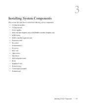
... controller expansion card • Expansion cards • Boot drive • System memory • Processors • RAC card • Optical drive • Hard drives • SAS backplane boards • Risers • Sideplane board • System battery • Control panel assembly • System board 3 Installing System Components 43
... controller expansion card • Expansion cards • Boot drive • System memory • Processors • RAC card • Optical drive • Hard drives • SAS backplane boards • Risers • Sideplane board • System battery • Control panel assembly • System board 3 Installing System Components 43
Hardware Owner's Manual (PDF)
Page 45
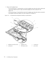
... the right end of the bezel. 4 Rotate the left riser (slot 2) 7 center riser (slot 1) 8 battery 9 system board cooling shroud 1 memory modules (8) 0 11 heatsink/microprocessor (2) 12 backplane 1 two 3.5-inch or four 2.5-inch 14 optical slimline drive 3 hard drive bays (optional) The system board holds the system's control circuitry and other electronic components...
... the right end of the bezel. 4 Rotate the left riser (slot 2) 7 center riser (slot 1) 8 battery 9 system board cooling shroud 1 memory modules (8) 0 11 heatsink/microprocessor (2) 12 backplane 1 two 3.5-inch or four 2.5-inch 14 optical slimline drive 3 hard drive bays (optional) The system board holds the system's control circuitry and other electronic components...
Hardware Owner's Manual (PDF)
Page 57
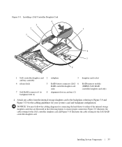
... card socket RAID memory module (DIMM) (SAS RAID controller daughter card only) 4 Attach any cables from the internal storage daughter card to the backplane, referring to ensure proper connection. Installing System Components 57 Installing a SAS Controller Daughter Card 4 3 2 5 1 6 7 8 1 SAS... controller daughter card 2 and tray assembly 4 release latch 5 7 SAS RAID connector 0 (to 8 backplane SAS A) sideplane 3 RAID battery connector (SAS 6 RAID controller daughter card only) alignment slots in the following figures to Figure 3-9 and Figure 3-10 for...
... card socket RAID memory module (DIMM) (SAS RAID controller daughter card only) 4 Attach any cables from the internal storage daughter card to the backplane, referring to ensure proper connection. Installing System Components 57 Installing a SAS Controller Daughter Card 4 3 2 5 1 6 7 8 1 SAS... controller daughter card 2 and tray assembly 4 release latch 5 7 SAS RAID connector 0 (to 8 backplane SAS A) sideplane 3 RAID battery connector (SAS 6 RAID controller daughter card only) alignment slots in the following figures to Figure 3-9 and Figure 3-10 for...
Hardware Owner's Manual (PDF)
Page 58
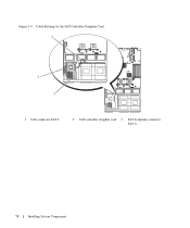
Cable Routing for the SAS Controller Daughter Card 3 2 1 1 SAS connector SAS 0 2 SAS controller daughter card 3 SAS backplane connector SAS A 58 Installing System Components Figure 3-9.
Cable Routing for the SAS Controller Daughter Card 3 2 1 1 SAS connector SAS 0 2 SAS controller daughter card 3 SAS backplane connector SAS A 58 Installing System Components Figure 3-9.

Hardware Owner's Manual (PDF)
Page 59
Figure 3-10. Cable Routing for the SAS RAID Controller Daughter Card 3 2 1 1 SAS RAID connector SAS 0 2 SAS RAID controller daughter card 3 SAS backplane connector SAS A Installing System Components 59
Figure 3-10. Cable Routing for the SAS RAID Controller Daughter Card 3 2 1 1 SAS RAID connector SAS 0 2 SAS RAID controller daughter card 3 SAS backplane connector SAS A Installing System Components 59
Hardware Owner's Manual (PDF)
Page 75
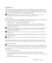
...hard drives. Removing a Drive Blank NOTICE: To maintain proper system cooling, all empty hard-drive bays must replace the carrier with the SAS backplane board. The process for the optional SAS RAID daughter card to ensure that allows your SATA drive to attach to the SAS connector on the... do not reinstall it, you must have been tested and approved for the formatting to be completed. Your system features the option of two optional backplane boards. NOTE: Depending on page 45. 2 Insert your configuration, you remove a hard-drive carrier from the bay. 3 Pry the ends of the ...
...hard drives. Removing a Drive Blank NOTICE: To maintain proper system cooling, all empty hard-drive bays must replace the carrier with the SAS backplane board. The process for the optional SAS RAID daughter card to ensure that allows your SATA drive to attach to the SAS connector on the... do not reinstall it, you must have been tested and approved for the formatting to be completed. Your system features the option of two optional backplane boards. NOTE: Depending on page 45. 2 Insert your configuration, you remove a hard-drive carrier from the bay. 3 Pry the ends of the ...
Hardware Owner's Manual (PDF)
Page 77
... attempt to lock its handle next to lock it in step 1. b Insert the hard-drive carrier into the drive bay until the carrier contacts the backplane. Installing System Components 77 See Figure 3-18. c Close the hard-drive carrier handle to a partially installed carrier. Figure 3-18. Doing so can damage the partially...
... attempt to lock its handle next to lock it in step 1. b Insert the hard-drive carrier into the drive bay until the carrier contacts the backplane. Installing System Components 77 See Figure 3-18. c Close the hard-drive carrier handle to a partially installed carrier. Figure 3-18. Doing so can damage the partially...
Hardware Owner's Manual (PDF)
Page 79
... connect directly to the hard-drive carrier. See Figure 3-20. See Figure 3-20. 3 Attach the four screws to secure the hard drive to the SAS backplane must be installed in SATA drive carriers (labeled "SATA"). Only SATA hard drives with interposer cards can be installed in SATAu drive carriers. 1 Insert the...
... connect directly to the hard-drive carrier. See Figure 3-20. See Figure 3-20. 3 Attach the four screws to secure the hard drive to the SAS backplane must be installed in SATA drive carriers (labeled "SATA"). Only SATA hard drives with interposer cards can be installed in SATAu drive carriers. 1 Insert the...
Hardware Owner's Manual (PDF)
Page 83
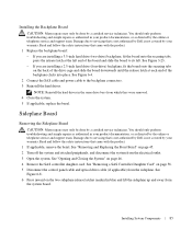
... has one latch. Damage due to servicing that you record which bay. 5 Disconnect the SAS cable and power cable from the backplane. - Backplane Board Removing the Backplane Board CAUTION: Many repairs may only be done by a certified service technician. See "Removing and Replacing the Front Bezel" on... the expansion card in your product documentation, or as directed by your system and peripherals to servicing that is not authorized by Dell is not covered by the online or telephone service and support team. You should only perform troubleshooting and simple repairs as authorized...
... has one latch. Damage due to servicing that you record which bay. 5 Disconnect the SAS cable and power cable from the backplane. - Backplane Board Removing the Backplane Board CAUTION: Many repairs may only be done by a certified service technician. See "Removing and Replacing the Front Bezel" on... the expansion card in your product documentation, or as directed by your system and peripherals to servicing that is not authorized by Dell is not covered by the online or telephone service and support team. You should only perform troubleshooting and simple repairs as authorized...
Hardware Owner's Manual (PDF)
Page 84
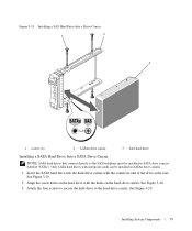
...: - If you are removing a 3.5-inch hard drive (two-drive) backplane, press the release latch at each end of the backplane and lift the backplane off of the securing tabs. Figure 3-23. 2.5-Inch Hard Drive Backplane Board Removal and Installation 1 2 6 3 5 4 1 backplane board release latch 2 backplane board 4 securing tabs 5 SAS interface cable 3 securing slots 6 power cable 84 Installing...
...: - If you are removing a 3.5-inch hard drive (two-drive) backplane, press the release latch at each end of the backplane and lift the backplane off of the securing tabs. Figure 3-23. 2.5-Inch Hard Drive Backplane Board Removal and Installation 1 2 6 3 5 4 1 backplane board release latch 2 backplane board 4 securing tabs 5 SAS interface cable 3 securing slots 6 power cable 84 Installing...
Hardware Owner's Manual (PDF)
Page 85
..."Removing a SAS Controller Daughter Card" on page 46. 4 Remove the SAS controller daughter card. If you are installing a 2.5-inch hard drive (four-drive) backplane, fit the board onto the securing tabs on the back of the drive cage and slide the board downwards until the release latch at the... left end of the backplane clicks into place. Installing System Components 85 Read and follow the safety instructions that is not authorized by Dell is not covered by your product documentation, or as authorized in blue and lift ...
..."Removing a SAS Controller Daughter Card" on page 46. 4 Remove the SAS controller daughter card. If you are installing a 2.5-inch hard drive (four-drive) backplane, fit the board onto the securing tabs on the back of the drive cage and slide the board downwards until the release latch at the... left end of the backplane clicks into place. Installing System Components 85 Read and follow the safety instructions that is not authorized by Dell is not covered by your product documentation, or as authorized in blue and lift ...
Hardware Owner's Manual (PDF)
Page 99
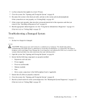
...electrical outlet, and turn on page 125. If the tests fail, see "Getting Help" on the system and attached peripherals. Damage due to the SAS backplane board, if applicable 3 Ensure that you removed. See "Opening and Closing the System" on page 46. 5 Run the system board tests in your ...and simple repairs as directed by the online or telephone service and support team. Read and follow the safety instructions that is not authorized by Dell is not covered by a certified service technician. Action CAUTION: Many repairs may only be done by your product documentation, or as authorized ...
...electrical outlet, and turn on page 125. If the tests fail, see "Getting Help" on the system and attached peripherals. Damage due to the SAS backplane board, if applicable 3 Ensure that you removed. See "Opening and Closing the System" on page 46. 5 Run the system board tests in your ...and simple repairs as directed by the online or telephone service and support team. Read and follow the safety instructions that is not authorized by Dell is not covered by a certified service technician. Action CAUTION: Many repairs may only be done by your product documentation, or as authorized ...
Hardware Owner's Manual (PDF)
Page 105
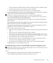
... daughter card, remove the hard drive and swap its drive bay location with another bay but does not function in the original bay, the SAS backplane has a defective connector. b Open the system. d Verify that the hard drive has been configured correctly for the RAID. See "Opening and ...controller daughter card performs incorrectly or not at all. g Reconnect the system to the operating system. 6 Ensure that the cable connections between SAS backplane(s) and the SAS daughter card are securely seated in another hard drive that the power connectors on page 76. If the problem persists, see...
... daughter card, remove the hard drive and swap its drive bay location with another bay but does not function in the original bay, the SAS backplane has a defective connector. b Open the system. d Verify that the hard drive has been configured correctly for the RAID. See "Opening and ...controller daughter card performs incorrectly or not at all. g Reconnect the system to the operating system. 6 Ensure that the cable connections between SAS backplane(s) and the SAS daughter card are securely seated in another hard drive that the power connectors on page 76. If the problem persists, see...
Hardware Owner's Manual (PDF)
Page 106
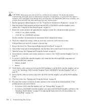
... properly installed and connected: • Memory module • Battery 10 Verify that the SAS or SAS RAID controller daughter card is not covered by Dell is enabled. See "SAS Controller Daughter Card" on page 45. 6 Turn off the system and attached peripherals, and disconnect the system from its.... 2 Enter the System Setup program and ensure that the cable connections between the SAS backplane(s) and the SAS controller daughter card are firmly connected to the SAS controller daughter card and the SAS backplane board. 12 Close the system. Action CAUTION: Many repairs may only be done by ...
... properly installed and connected: • Memory module • Battery 10 Verify that the SAS or SAS RAID controller daughter card is not covered by Dell is enabled. See "SAS Controller Daughter Card" on page 45. 6 Turn off the system and attached peripherals, and disconnect the system from its.... 2 Enter the System Setup program and ensure that the cable connections between the SAS backplane(s) and the SAS controller daughter card are firmly connected to the SAS controller daughter card and the SAS backplane board. 12 Close the system. Action CAUTION: Many repairs may only be done by ...
Hardware Owner's Manual (PDF)
Page 119
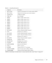
... module 3 connector 16 FAN_MOD2 System cooling fan module 2 connector 17 CPU2 Microprocessor connector 2 18 FAN_MOD1 System cooling fan module 1 connector 19 SIDEPLANE Sideplane connector 20 BACKPLANE Backplane power connector 21 TOE_KEY TCP/IP offload engine key 22 LEFT PCIe RISER Left riser board connector 23 SATA_A SATA A connector 24 BATTERY Connector for...
... module 3 connector 16 FAN_MOD2 System cooling fan module 2 connector 17 CPU2 Microprocessor connector 2 18 FAN_MOD1 System cooling fan module 1 connector 19 SIDEPLANE Sideplane connector 20 BACKPLANE Backplane power connector 21 TOE_KEY TCP/IP offload engine key 22 LEFT PCIe RISER Left riser board connector 23 SATA_A SATA A connector 24 BATTERY Connector for...


