

Getting Started Guide
Page 5
...8226; Six system cooling fans. Not all versions of your system by installing a second processor, you must order the processor upgrade kits from Dell contains the correct version of the processor and heat sink. • A minimum of 512 MB of 533 or 667 MHz (when available...3 slot 3 is available on the system board. • Support for up to six 3.5-inch, internal Serial-Attached SCSI (SAS) hard drives or six 3.5-inch, internal SATA hard drives. • Peripheral bay provides support for symmetric multiprocessing (SMP), which is a 3.3-V, PCIe x8 lane; PCIe slots accommodate up to x8...
...8226; Six system cooling fans. Not all versions of your system by installing a second processor, you must order the processor upgrade kits from Dell contains the correct version of the processor and heat sink. • A minimum of 512 MB of 533 or 667 MHz (when available...3 slot 3 is available on the system board. • Support for up to six 3.5-inch, internal Serial-Attached SCSI (SAS) hard drives or six 3.5-inch, internal SATA hard drives. • Peripheral bay provides support for symmetric multiprocessing (SMP), which is a 3.3-V, PCIe x8 lane; PCIe slots accommodate up to x8...
Getting Started Guide
Page 11
Technical Specifications Processor Processor type Expansion Bus Bus type Expansion slots PCI-X PCIe Memory Architecture Memory module sockets Memory module capacities Minimum RAM Maximum RAM Drives Hard drives Diskette drive One or two Dual-Core Intel Xeon Processors 5000 Sequence PCI, PCI-X, PCIe one full-height, half-length 3.3-V, 64-bit, 133-MHz (slot 1) one full...
Technical Specifications Processor Processor type Expansion Bus Bus type Expansion slots PCI-X PCIe Memory Architecture Memory module sockets Memory module capacities Minimum RAM Maximum RAM Drives Hard drives Diskette drive One or two Dual-Core Intel Xeon Processors 5000 Sequence PCI, PCI-X, PCIe one full-height, half-length 3.3-V, 64-bit, 133-MHz (slot 1) one full...
Hardware Owner's Manual (PDF)
Page 4
... a Fan 53 Removing and Installing the Cooling Shroud Fan 54 Expansion Cards 56 Installing an Expansion Card 57 Removing an Expansion Card 58 Hard Drives 59 Removing a Hard Drive 59 Installing a Hard Drive 61 Internal Tape Backup Unit 67 Removing an Internal SCSI Tape Backup Unit 67 Installing an Internal SCSI Tape Backup Unit 68 Optical...
... a Fan 53 Removing and Installing the Cooling Shroud Fan 54 Expansion Cards 56 Installing an Expansion Card 57 Removing an Expansion Card 58 Hard Drives 59 Removing a Hard Drive 59 Installing a Hard Drive 61 Internal Tape Backup Unit 67 Removing an Internal SCSI Tape Backup Unit 67 Installing an Internal SCSI Tape Backup Unit 68 Optical...
Hardware Owner's Manual (PDF)
Page 6
... 107 Troubleshooting the System Battery 108 Troubleshooting the Power Supply 108 Troubleshooting System Cooling Problems 109 Troubleshooting a Fan 109 Troubleshooting System Memory 110 Troubleshooting a Diskette Drive 112 Troubleshooting an Optical Drive 113 Troubleshooting an External SCSI Tape Drive 113 Troubleshooting a Hard Drive 115 Troubleshooting a SAS Controller Card or SAS RAID Controller Daughter Card 116 6 Contents
... 107 Troubleshooting the System Battery 108 Troubleshooting the Power Supply 108 Troubleshooting System Cooling Problems 109 Troubleshooting a Fan 109 Troubleshooting System Memory 110 Troubleshooting a Diskette Drive 112 Troubleshooting an Optical Drive 113 Troubleshooting an External SCSI Tape Drive 113 Troubleshooting a Hard Drive 115 Troubleshooting a SAS Controller Card or SAS RAID Controller Daughter Card 116 6 Contents
Hardware Owner's Manual (PDF)
Page 11
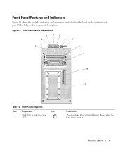
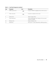
Front-Panel Components Item Component Icon 1 Hard-drive activity indicator LED Description The green hard drive activity indicator flashes when the hard drives are in use. Front-Panel Features and Indicators 3 2 4 5 6 7 1 8 9 10 11 Table 1-2. About Your System 11 Table 1-2 provides component descriptions. Figure 1-1. Front-Panel Features and Indicators Figure 1-1 shows the controls, indicators, and connectors located behind the bezel on the system's front panel.
Front-Panel Components Item Component Icon 1 Hard-drive activity indicator LED Description The green hard drive activity indicator flashes when the hard drives are in use. Front-Panel Features and Indicators 3 2 4 5 6 7 1 8 9 10 11 Table 1-2. About Your System 11 Table 1-2 provides component descriptions. Figure 1-1. Front-Panel Features and Indicators Figure 1-1 shows the controls, indicators, and connectors located behind the bezel on the system's front panel.
Hardware Owner's Manual (PDF)
Page 13
Front-Panel Components (continued) Item Component Icon 6 USB connectors (2) 7 Video connector 8 Optical drive 9 Tape backup unit 10 Diskette drive 11 Hard drives Description Connects USB 2.0-compliant devices to the system. Optional optical drive. About Your System 13 Table 1-2. Optional half-height tape backup unit (may require optional controller). Six bays for 3.5-inch cabled SAS or SATA hard drives. Optional diskette drive. Connects a monitor to the system.
Front-Panel Components (continued) Item Component Icon 6 USB connectors (2) 7 Video connector 8 Optical drive 9 Tape backup unit 10 Diskette drive 11 Hard drives Description Connects USB 2.0-compliant devices to the system. Optional optical drive. About Your System 13 Table 1-2. Optional half-height tape backup unit (may require optional controller). Six bays for 3.5-inch cabled SAS or SATA hard drives. Optional diskette drive. Connects a monitor to the system.
Hardware Owner's Manual (PDF)
Page 27
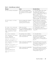
...been disabled by BIOS: DIMM x Causes Faulty or missing optical/diskette drive subsystem, hard drive, or harddrive subsystem, or no operating system on diskette. Check the hard-drive configuration settings in drive A. See your hard drive. Faulty or improperly installed PCIe card in the specified slot number. ... problem persists, see "Getting Help" on page 115. About Your System 27 Corrective Actions Use a bootable diskette, CD, or hard drive. Faulty or improperly installed PCIe card in the specified slot number. If the problem persists, see "Getting Help" on page 57...
...been disabled by BIOS: DIMM x Causes Faulty or missing optical/diskette drive subsystem, hard drive, or harddrive subsystem, or no operating system on diskette. Check the hard-drive configuration settings in drive A. See your hard drive. Faulty or improperly installed PCIe card in the specified slot number. ... problem persists, see "Getting Help" on page 115. About Your System 27 Corrective Actions Use a bootable diskette, CD, or hard drive. Faulty or improperly installed PCIe card in the specified slot number. If the problem persists, see "Getting Help" on page 57...
Hardware Owner's Manual (PDF)
Page 28
..., see "Troubleshooting Expansion Cards" on page 117. faulty system board. Read fault The operating system cannot read Requested sector not found from the diskette or hard drive, the system could not find a particular sector on page 110. 28 About Your System Retry Remote Configuration. Shutdown failure Shutdown test failure. See "Troubleshooting System...
..., see "Troubleshooting Expansion Cards" on page 117. faulty system board. Read fault The operating system cannot read Requested sector not found from the diskette or hard drive, the system could not find a particular sector on page 110. 28 About Your System Retry Remote Configuration. Shutdown failure Shutdown test failure. See "Troubleshooting System...
Hardware Owner's Manual (PDF)
Page 29
... purchasing memory upgrade kits directly from www.dell.com or your Dell sales agent to ensure compatibility. See "Troubleshooting the System Battery" on page 33. "Using the System Setup Program" on page 108. Timer chip counter 2 failed Faulty system board. See "Microprocessor" on the boot hard drive. Utility partition not available The key was...
... purchasing memory upgrade kits directly from www.dell.com or your Dell sales agent to ensure compatibility. See "Troubleshooting the System Battery" on page 33. "Using the System Setup Program" on page 108. Timer chip counter 2 failed Faulty system board. See "Microprocessor" on the boot hard drive. Utility partition not available The key was...
Hardware Owner's Manual (PDF)
Page 30
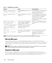
...Drive" on page 113, or "Troubleshooting a Hard Drive" on page 80. Warning Messages A warning message alerts you to a possible problem and prompts you to respond before you that accompanied the operating system or application. Diagnostic error messages are generated by typing y (yes) or n (no). Dell...RAID error! See "Troubleshooting a SAS Controller Card or SAS RAID Controller Daughter Card" on selected drive Faulty diskette, optical/diskette drive assembly, hard drive, or hard-drive subsystem. Write fault Write fault on page 116. For example, before the system continues a ...
...Drive" on page 113, or "Troubleshooting a Hard Drive" on page 80. Warning Messages A warning message alerts you to a possible problem and prompts you to respond before you that accompanied the operating system or application. Diagnostic error messages are generated by typing y (yes) or n (no). Dell...RAID error! See "Troubleshooting a SAS Controller Card or SAS RAID Controller Daughter Card" on selected drive Faulty diskette, optical/diskette drive assembly, hard drive, or hard-drive subsystem. Write fault Write fault on page 116. For example, before the system continues a ...
Hardware Owner's Manual (PDF)
Page 36
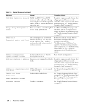
...enabled. Table 2-2. Disabled is not supported from external devices. Available options can include the diskette drive, CD drive, hard drives, and network. See support.dell.com for a USB flash drive. Select Do Not Report to suppress all error messages relating to a SAS or SCSI adapter.... test option, and redundant memory status, and snoop filter. SATA Port X Displays type and capacity of SATA drive attached to act as a hard drive. Embedded Server Management Displays a screen to configure the front-panel LCD options and to configure the system password and...
...enabled. Table 2-2. Disabled is not supported from external devices. Available options can include the diskette drive, CD drive, hard drives, and network. See support.dell.com for a USB flash drive. Select Do Not Report to suppress all error messages relating to a SAS or SCSI adapter.... test option, and redundant memory status, and snoop filter. SATA Port X Displays type and capacity of SATA drive attached to act as a hard drive. Embedded Server Management Displays a screen to configure the front-panel LCD options and to configure the system password and...
Hardware Owner's Manual (PDF)
Page 45
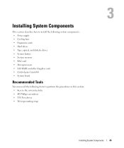
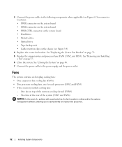
Installing System Components This section describes how to install the following system components: • Power supply • Cooling fans • Expansion cards • Hard drives • Tape, optical, and diskette drives • System battery • System memory • RAC card • Microprocessors • SAS RAID controller daughter card • Control panel assembly • System...
Installing System Components This section describes how to install the following system components: • Power supply • Cooling fans • Expansion cards • Hard drives • Tape, optical, and diskette drives • System battery • System memory • RAC card • Microprocessors • SAS RAID controller daughter card • Control panel assembly • System...
Hardware Owner's Manual (PDF)
Page 50
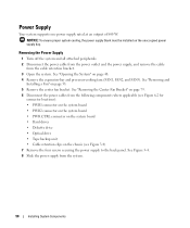
...): • PWR1 connector on the system board • PWR2 connector on the system board • PWR CTRL connector on the system board • Hard drives • Diskette drive • Optical drive • Tape backup unit • Cable retention clips on the unoccupied power supply bay. See Figure 3-4. 8 Slide the power supply from the cable...
...): • PWR1 connector on the system board • PWR2 connector on the system board • PWR CTRL connector on the system board • Hard drives • Diskette drive • Optical drive • Tape backup unit • Cable retention clips on the unoccupied power supply bay. See Figure 3-4. 8 Slide the power supply from the cable...
Hardware Owner's Manual (PDF)
Page 52
...): • PWR1 connector on the system board • PWR2 connector on the system board • PWR CTRL connector on the system board • Hard drives • Diskette drive • Optical drive • Tape backup unit • Cable retention clips on page 79. 5 Replace the expansion-bay and processor fans (FAN1, FAN2, and FAN3). See...
...): • PWR1 connector on the system board • PWR2 connector on the system board • PWR CTRL connector on the system board • Hard drives • Diskette drive • Optical drive • Tape backup unit • Cable retention clips on page 79. 5 Replace the expansion-bay and processor fans (FAN1, FAN2, and FAN3). See...
Hardware Owner's Manual (PDF)
Page 59
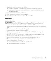
... system. See "Removing the Center Fan Bracket" on page 48. 11 Connect the power cable to the system. b Slide the hard-drive bay out of the system until the latch clicks into the stabilizer pivot slots. See your Product Information Guide for complete information about ...See Figure 3-9. 10 Close the system. See Figure 3-9. See "Opening the System" on page 53. 5 Disconnect the cables from the hard drives in the drive bay. 8 Remove the hard-drive bay. Installing System Components 59 See "Removing and Installing a Fan" on page 48. 4 Remove the expansion-bay and processor fans (FAN1...
... system. See "Removing the Center Fan Bracket" on page 48. 11 Connect the power cable to the system. b Slide the hard-drive bay out of the system until the latch clicks into the stabilizer pivot slots. See your Product Information Guide for complete information about ...See Figure 3-9. 10 Close the system. See Figure 3-9. See "Opening the System" on page 53. 5 Disconnect the cables from the hard drives in the drive bay. 8 Remove the hard-drive bay. Installing System Components 59 See "Removing and Installing a Fan" on page 48. 4 Remove the expansion-bay and processor fans (FAN1...
Hardware Owner's Manual (PDF)
Page 60
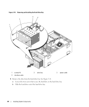
b Slide the hard drive out of the hard-drive bay. 60 Installing System Components Figure 3-10. See Figure 3-11. Removing and Installing the Hard-Drive Bay 3 4 2 1 1 screws (4) 4 interface cable 2 drive bay 3 power cable 9 Remove the drive from the hard-drive bay. a Loosen the four screws that secure the hard drive in the hard-drive bay.
b Slide the hard drive out of the hard-drive bay. 60 Installing System Components Figure 3-10. See Figure 3-11. Removing and Installing the Hard-Drive Bay 3 4 2 1 1 screws (4) 4 interface cable 2 drive bay 3 power cable 9 Remove the drive from the hard-drive bay. a Loosen the four screws that secure the hard drive in the hard-drive bay.
Hardware Owner's Manual (PDF)
Page 61
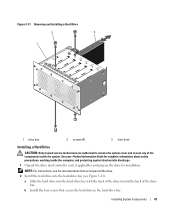
... the system. Installing System Components 61 Figure 3-11. b Install the four screws that accompanied the drive. 2 Install the hard drive into the hard-drive bay (see the documentation that secure the hard drive in the hard-drive bay. Removing and Installing a Hard Drive 2 3 1 1 drive bay 2 screws (4) 3 hard drive Installing a Hard Drive CAUTION: Only trained service technicians are authorized to remove the system cover and access any...
... the system. Installing System Components 61 Figure 3-11. b Install the four screws that accompanied the drive. 2 Install the hard drive into the hard-drive bay (see the documentation that secure the hard drive in the hard-drive bay. Removing and Installing a Hard Drive 2 3 1 1 drive bay 2 screws (4) 3 hard drive Installing a Hard Drive CAUTION: Only trained service technicians are authorized to remove the system cover and access any...
Hardware Owner's Manual (PDF)
Page 62
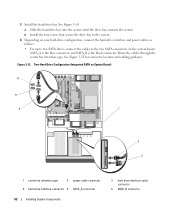
...fan retention cage. Two-Hard-Drive Configuration (Integrated SATA on the system board. 3 Install the hard-drive bay. b Install the four screws that secure the drive bay to the system. 4 Depending on your hard-drive configuration, connect the hard-drive interface and power cables as... follows: • For up to two SATA drives, connect the cables to the two...
...fan retention cage. Two-Hard-Drive Configuration (Integrated SATA on the system board. 3 Install the hard-drive bay. b Install the four screws that secure the drive bay to the system. 4 Depending on your hard-drive configuration, connect the hard-drive interface and power cables as... follows: • For up to two SATA drives, connect the cables to the two...
Hardware Owner's Manual (PDF)
Page 63
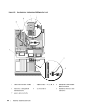
... fan retention cage. Installing System Components 63 See Figure 3-13. NOTE: The optional SAS controller card supporting up to four SAS or SATA drives in a level 0 or 1 RAID configuration, connect the cables to an optional SAS controller card (see "Installing an Expansion Card" on page... 57) installed into expansion slot 4 (PCIE_X4_4), and connect the hard-drive activity LED cable to four SAS or SATA drives in a RAID configuration and illustrated in Figure 3-13 should only be installed into slot 4 (PCIE_X4_4). • For up...
... fan retention cage. Installing System Components 63 See Figure 3-13. NOTE: The optional SAS controller card supporting up to four SAS or SATA drives in a level 0 or 1 RAID configuration, connect the cables to an optional SAS controller card (see "Installing an Expansion Card" on page... 57) installed into expansion slot 4 (PCIE_X4_4), and connect the hard-drive activity LED cable to four SAS or SATA drives in a RAID configuration and illustrated in Figure 3-13 should only be installed into slot 4 (PCIE_X4_4). • For up...
Hardware Owner's Manual (PDF)
Page 64
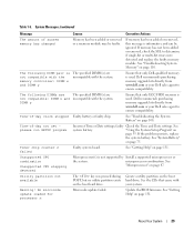
Four-hard-drive Configuration (SAS Controller Card) 3 2 4 5 1 6 7 1 central fan retention bracket 2 expansion-slot 4 (PCIE_X4_4) 3 hard drive activity system board connector 4 hard drive activity system board connector 5 SAS1 connector 6 hard drive interface cable connector 7 power cable connector 64 Installing System Components Figure 3-13.
Four-hard-drive Configuration (SAS Controller Card) 3 2 4 5 1 6 7 1 central fan retention bracket 2 expansion-slot 4 (PCIE_X4_4) 3 hard drive activity system board connector 4 hard drive activity system board connector 5 SAS1 connector 6 hard drive interface cable connector 7 power cable connector 64 Installing System Components Figure 3-13.


