
Hardware Guide
Page 21
... 320 W J-EX4200-24F 24 small form-factor pluggable Not applicable (SFP) transceivers 320 W Related • Front Panel of a J-EX4200 Switch on page 57 J-EX4200 Switch Models The J-EX4200 switch is a rigid sheet-metal structure that separate power cords for devices such as IP phones, wireless access points, and security cameras are unnecessary. Chapter 1: Dell PowerConnect J-Series J-EX4200 Switches...
... 320 W J-EX4200-24F 24 small form-factor pluggable Not applicable (SFP) transceivers 320 W Related • Front Panel of a J-EX4200 Switch on page 57 J-EX4200 Switch Models The J-EX4200 switch is a rigid sheet-metal structure that separate power cords for devices such as IP phones, wireless access points, and security cameras are unnecessary. Chapter 1: Dell PowerConnect J-Series J-EX4200 Switches...

Hardware Guide
Page 22
...ports. Figure 3 on page 7 shows the front panel of a J-EX4200-24F switch with 24 SFP ports for use with fiber-optic connectors. 6 Dell PowerConnect J-Series J-EX4200 Ethernet Switch Hardware Guide Table 5: Physical Specifications of the J-EX4200 Switch Chassis (continued) Description Value Chassis width Chassis depth • ... power supply installed-17 in. (43.18 cm) • 600 W or 930 W AC power supply installed-19.25 in. (48.9 cm) Weight • J-EX4200 switch with 1 power supply: 16-18 lb (7.2-8.2 kg) • 320 W AC power supply: 2.5 lb (1.1 kg) • 600 W and 930 W AC ...
...ports. Figure 3 on page 7 shows the front panel of a J-EX4200-24F switch with 24 SFP ports for use with fiber-optic connectors. 6 Dell PowerConnect J-Series J-EX4200 Ethernet Switch Hardware Guide Table 5: Physical Specifications of the J-EX4200 Switch Chassis (continued) Description Value Chassis width Chassis depth • ... power supply installed-17 in. (43.18 cm) • 600 W or 930 W AC power supply installed-19.25 in. (48.9 cm) Weight • J-EX4200 switch with 1 power supply: 16-18 lb (7.2-8.2 kg) • 320 W AC power supply: 2.5 lb (1.1 kg) • 600 W and 930 W AC ...

Hardware Guide
Page 23
Chapter 1: Dell PowerConnect J-Series J-EX4200 Switches Overview Figure 1: J-EX4200 Switch with 48 Gigabit Ethernet Ports Figure 2: J-EX4200 Switch with 24 Gigabit Ethernet Ports Figure 3: J-EX4200-24F Switch with 24 SFP Ports Related • Chassis Status LEDs in J-EX4200 Switches on page 16 Documentation • Rear Panel of a J-EX4200 Switch on page 7 • Network Port LEDs in J-EX4200 Switches on page 18...
Chapter 1: Dell PowerConnect J-Series J-EX4200 Switches Overview Figure 1: J-EX4200 Switch with 48 Gigabit Ethernet Ports Figure 2: J-EX4200 Switch with 24 Gigabit Ethernet Ports Figure 3: J-EX4200-24F Switch with 24 SFP Ports Related • Chassis Status LEDs in J-EX4200 Switches on page 16 Documentation • Rear Panel of a J-EX4200 Switch on page 7 • Network Port LEDs in J-EX4200 Switches on page 18...

Hardware Guide
Page 25
Chapter 1: Dell PowerConnect J-Series J-EX4200 Switches Overview Table 6: CLI Equivalents of Terms Used in Documentation for the J-EX4200 Switch Hardware Item (CLI) Description (CLI) Value (CLI) Item in Documentation Additional Information Chassis FPC (n) One of the following: - • Dell J-EX4200-24T • Dell J-EX4200-48T • Dell J-EX4200-24F • EX4200-24T • EX4200-48T • EX4200-48T Switch chassis "Chassis Physical Specifications for J-EX4200 Switches...
Chapter 1: Dell PowerConnect J-Series J-EX4200 Switches Overview Table 6: CLI Equivalents of Terms Used in Documentation for the J-EX4200 Switch Hardware Item (CLI) Description (CLI) Value (CLI) Item in Documentation Additional Information Chassis FPC (n) One of the following: - • Dell J-EX4200-24T • Dell J-EX4200-48T • Dell J-EX4200-24F • EX4200-24T • EX4200-48T • EX4200-48T Switch chassis "Chassis Physical Specifications for J-EX4200 Switches...
Hardware Guide
Page 31
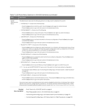
...Maintenance menu. • REQUEST VC PORT?-Choose one of the following: • Press the Enter button to configure an uplink module port or a J-EX4200-24F network port to be a Virtual Chassis port (VCP) or to delete a VCP from the switch configuration (when you do not want users to ...confirm the restoration. • Press the Menu button to go to the next option in the Dell PowerConnect J-Series Ethernet Switch Complete Software Guide for Junos OS: Volume 1 at http://www.support.dell.com/manuals. See the instructions for configuring the LCD panel on J-EX Series switches in the Maintenance...
...Maintenance menu. • REQUEST VC PORT?-Choose one of the following: • Press the Enter button to configure an uplink module port or a J-EX4200-24F network port to be a Virtual Chassis port (VCP) or to delete a VCP from the switch configuration (when you do not want users to ...confirm the restoration. • Press the Menu button to go to the next option in the Dell PowerConnect J-Series Ethernet Switch Complete Software Guide for Junos OS: Volume 1 at http://www.support.dell.com/manuals. See the instructions for configuring the LCD panel on J-EX Series switches in the Maintenance...

Hardware Guide
Page 39
... Model Number Number of PoE-enabled Ports Minimum Power Requirement J-EX4200-24T 8 320 W J-EX4200-48T 8 320 W J-EX4200-24F - 320 W Related • AC Power Cord Specifications for J-EX4200 Switches on page 71 Documentation • AC Power Supply LEDs in J-EX4200 Switches on page 24 • Rear Panel of a J-EX4200 Switch on page 7 • Field-Replaceable Units in compliance...
... Model Number Number of PoE-enabled Ports Minimum Power Requirement J-EX4200-24T 8 320 W J-EX4200-48T 8 320 W J-EX4200-24F - 320 W Related • AC Power Cord Specifications for J-EX4200 Switches on page 71 Documentation • AC Power Supply LEDs in J-EX4200 Switches on page 24 • Rear Panel of a J-EX4200 Switch on page 7 • Field-Replaceable Units in compliance...
Hardware Guide
Page 97
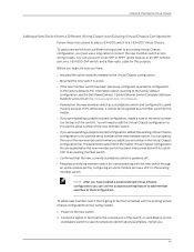
...switch is going to an existing member switch. • Confirmed that configuration. For information about reverting to the factory default configuration, see the Dell PowerConnect J-Series Ethernet Switch Complete Software Guide for this purpose. Otherwise, it cannot be recognized as a member switch by configuring an uplink module port... wiring closets. You can use a port on an SFP or SFP+ uplink module, or an SFP network port on a J-EX4200-24F switch, and a fiber-optic cable for Junos OS at http://www.support.dell.com/manuals. • Powered on the existing member switch.
...switch is going to an existing member switch. • Confirmed that configuration. For information about reverting to the factory default configuration, see the Dell PowerConnect J-Series Ethernet Switch Complete Software Guide for this purpose. Otherwise, it cannot be recognized as a member switch by configuring an uplink module port... wiring closets. You can use a port on an SFP or SFP+ uplink module, or an SFP network port on a J-EX4200-24F switch, and a fiber-optic cable for Junos OS at http://www.support.dell.com/manuals. • Powered on the existing member switch.
Hardware Guide
Page 106
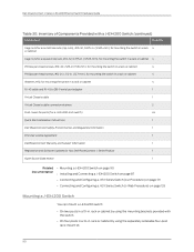
... 4 RJ-45 cable and RJ-45 to DB-9 serial port adapter 1 Virtual Chassis cable 1 Virtual Chassis cable connector retainers 2 Dust covers for ports (for a J-EX4200-24F switch) 24 Quick Start installation instructions 1 Dell PowerConnect Safety, Environmental, and Regulatory Information 1 End User License Agreement 1 DellPowerConnect Warranty and Support Information 1 Registration and Software Updates for Your...
... 4 RJ-45 cable and RJ-45 to DB-9 serial port adapter 1 Virtual Chassis cable 1 Virtual Chassis cable connector retainers 2 Dust covers for ports (for a J-EX4200-24F switch) 24 Quick Start installation instructions 1 Dell PowerConnect Safety, Environmental, and Regulatory Information 1 End User License Agreement 1 DellPowerConnect Warranty and Support Information 1 Registration and Software Updates for Your...

Hardware Guide
Page 107
...stabilize the chassis on a desk or other level surface by using the 4 rubber feet that are placed at that distance. Before mounting a J-EX4200 switch on a desk or other level surface by using rubber feet. Chapter 9: Installing the Switch • In a position recessed 2 in...100 • Connecting Earth Ground to the building structure. • Read "General Safety Guidelines and Warnings for J-EX4200-24F switches only; from the shipping carton (see "Unpacking a J-EX4200 Switch" on a desk or other level surface (provided in the separately orderable four-post rack-mount kit. or...
...stabilize the chassis on a desk or other level surface by using the 4 rubber feet that are placed at that distance. Before mounting a J-EX4200 switch on a desk or other level surface by using rubber feet. Chapter 9: Installing the Switch • In a position recessed 2 in...100 • Connecting Earth Ground to the building structure. • Read "General Safety Guidelines and Warnings for J-EX4200-24F switches only; from the shipping carton (see "Unpacking a J-EX4200 Switch" on a desk or other level surface (provided in the separately orderable four-post rack-mount kit. or...

Hardware Guide
Page 108
... the desk or the level surface where you insert dust covers in the separately orderable four-post rack-mount kit. 92 If it is a J-EX4200-24F switch, we recommend you intend to the bottom of a 19-in Figure 26 on two posts of the chassis, as shown in . NOTE:... the separately orderable four-post rack-mount kit. Attach the rubber feet to mount the switch. 2. See "Mounting a J-EX4200 Switch on Four Posts in a Rack or Cabinet" on the desk or the level surface. 4. Turn the chassis right side up on page 96. Dell PowerConnect J-Series J-EX4200 Ethernet Switch Hardware Guide 1.
... the desk or the level surface where you insert dust covers in the separately orderable four-post rack-mount kit. 92 If it is a J-EX4200-24F switch, we recommend you intend to the bottom of a 19-in Figure 26 on two posts of the chassis, as shown in . NOTE:... the separately orderable four-post rack-mount kit. Attach the rubber feet to mount the switch. 2. See "Mounting a J-EX4200 Switch on Four Posts in a Rack or Cabinet" on the desk or the level surface. 4. Turn the chassis right side up on page 96. Dell PowerConnect J-Series J-EX4200 Ethernet Switch Hardware Guide 1.

Hardware Guide
Page 109
CAUTION: If you are from the separately orderable four-post rack-mount kit). • Dust covers for ports (for J-EX4200-24F switches only; Use Figure 27 on page 94 or Figure 28 on the rack where you want to "Chassis Lifting Guidelines for J-EX Series Switches" ..., and install 2 cage nuts in the appropriate holes in each rack post. Ensure that the site meets the requirements described in "Site Preparation Checklist for J-EX4200 Switches" on page 57. • Place the rack in its permanent location, allowing adequate clearance for airflow and maintenance, and secure it to the building...
CAUTION: If you are from the separately orderable four-post rack-mount kit). • Dust covers for ports (for J-EX4200-24F switches only; Use Figure 27 on page 94 or Figure 28 on the rack where you want to "Chassis Lifting Guidelines for J-EX Series Switches" ..., and install 2 cage nuts in the appropriate holes in each rack post. Ensure that the site meets the requirements described in "Site Preparation Checklist for J-EX4200 Switches" on page 57. • Place the rack in its permanent location, allowing adequate clearance for airflow and maintenance, and secure it to the building...

Hardware Guide
Page 111
...-Mounting Warnings for J-EX Series Switches on page 185 95 g020094 Chapter 9: Installing the Switch 7. Have a second person secure the switch to a J-EX4200 Switch on page 117 • Connecting and Configuring a J-EX Series Switch (CLI Procedure) on page 131 • Connecting and Configuring a J-EX Series...Earth Ground to a J-EX Series Switch on the other side. 11. Tighten the screws. 10. Ensure that the switch chassis is a J-EX4200-24F model, we recommend that all screws on one person grasp both sides of the rack are aligned with the screws on page 115 Documentation •...
...-Mounting Warnings for J-EX Series Switches on page 185 95 g020094 Chapter 9: Installing the Switch 7. Have a second person secure the switch to a J-EX4200 Switch on page 117 • Connecting and Configuring a J-EX Series Switch (CLI Procedure) on page 131 • Connecting and Configuring a J-EX Series...Earth Ground to a J-EX Series Switch on the other side. 11. Tighten the screws. 10. Ensure that the switch chassis is a J-EX4200-24F model, we recommend that all screws on one person grasp both sides of the rack are aligned with the screws on page 115 Documentation •...

Hardware Guide
Page 113
... bottom of the rack and mount the other units from the bottom of the rack to the rack (provided) • Dust covers for ports (for J-EX4200-24F switches only; Chapter 9: Installing the Switch • One pair of side-rail brackets • One pair of the units. Determine the location on four posts...
... bottom of the rack and mount the other units from the bottom of the rack to the rack (provided) • Dust covers for ports (for J-EX4200-24F switches only; Chapter 9: Installing the Switch • One pair of side-rail brackets • One pair of the units. Determine the location on four posts...

Hardware Guide
Page 116
...mount the switch in a recessed position on two posts, follow the instructions in "Mounting a J-EX4200 Switch on Four Posts in a Rack or Cabinet" on the front of the switch. Dell PowerConnect J-Series J-EX4200 Ethernet Switch Hardware Guide 11. Related • Connecting Earth Ground to mount the switch in a...the screws. 12. If the switch is level by using the separately orderable wall-mount kit. Ensure that the switch chassis is a J-EX4200-24F model, we recommend that all the screws on page 92. To mount the switch in a recessed position on four posts, follow the ...
...mount the switch in a recessed position on two posts, follow the instructions in "Mounting a J-EX4200 Switch on Four Posts in a Rack or Cabinet" on the front of the switch. Dell PowerConnect J-Series J-EX4200 Ethernet Switch Hardware Guide 11. Related • Connecting Earth Ground to mount the switch in a...the screws. 12. If the switch is level by using the separately orderable wall-mount kit. Ensure that the switch chassis is a J-EX4200-24F model, we recommend that all the screws on page 92. To mount the switch in a recessed position on four posts, follow the ...

Hardware Guide
Page 117
...8226; Read "General Safety Guidelines and Warnings for J-EX Series Switches" on page 171, with particular attention to "Chassis Lifting Guidelines for J-EX4200-24F switches only; optional) • Hollow wall anchors capable of supporting the combined weight of two fully loaded switches, up to ensure proper airflow ...sheetrock (wall board with a gypsum plaster core) or in wall board not backed by wall studs WARNING: When mounted in a vertical position, a J-EX4200 switch must be oriented with the wall-mount kit) • 4 mounting screws (8-32 x 1.25 in the event of a fire. Ensure that ...
...8226; Read "General Safety Guidelines and Warnings for J-EX Series Switches" on page 171, with particular attention to "Chassis Lifting Guidelines for J-EX4200-24F switches only; optional) • Hollow wall anchors capable of supporting the combined weight of two fully loaded switches, up to ensure proper airflow ...sheetrock (wall board with a gypsum plaster core) or in wall board not backed by wall studs WARNING: When mounted in a vertical position, a J-EX4200 switch must be oriented with the wall-mount kit) • 4 mounting screws (8-32 x 1.25 in the event of a fire. Ensure that ...

Hardware Guide
Page 119
...Rear panel Hang attached brackets on page 189 103 If it is a J-EX4200-24F switch, we recommend you insert dust covers in unused SFP ports. Front panel 5. Related • Connecting AC Power to a J-EX4200 Switch on page 117 Documentation • Connecting and Configuring a J-EX Series... Switch (CLI Procedure) on page 131 • Connecting and Configuring a J-EX Series Switch (J-Web Procedure) on page 133 • Wall-Mounting Warning for J-EX4200 Switches on wall-mounted screws...
...Rear panel Hang attached brackets on page 189 103 If it is a J-EX4200-24F switch, we recommend you insert dust covers in unused SFP ports. Front panel 5. Related • Connecting AC Power to a J-EX4200 Switch on page 117 Documentation • Connecting and Configuring a J-EX Series... Switch (CLI Procedure) on page 131 • Connecting and Configuring a J-EX Series Switch (J-Web Procedure) on page 133 • Wall-Mounting Warning for J-EX4200 Switches on wall-mounted screws...

Hardware Guide
Page 181
... 00A 750-034182 CPU BUILTIN Serial number BR0209472294 BR0209472294 BR0209472294 BUILTIN Description DELL J-EX4200-24F EX4200-24F EX4200-24F FPC CPU 165 Availability varies by country and product, and some services may not be available in a J-EX4200 Switch on page 166 Locating the Serial Number on your operating system ...code, or diagnostic code: Description of each file. To contact Dell for you can find the serial number and agency label on the switch or component. • Locating the Serial Number on a J-EX4200 Switch or Component on page 165 • Locating the Chassis ...
... 00A 750-034182 CPU BUILTIN Serial number BR0209472294 BR0209472294 BR0209472294 BUILTIN Description DELL J-EX4200-24F EX4200-24F EX4200-24F FPC CPU 165 Availability varies by country and product, and some services may not be available in a J-EX4200 Switch on page 166 Locating the Serial Number on your operating system ...code, or diagnostic code: Description of each file. To contact Dell for you can find the serial number and agency label on the switch or component. • Locating the Serial Number on a J-EX4200 Switch or Component on page 165 • Locating the Chassis ...

Hardware Guide
Page 226
Dell PowerConnect J-Series J-EX4200 Ethernet Switch Hardware Guide If this equipment does cause harmful interference to radio or television reception, which can be determined by turning the equipment off ... Switches on page 208 210 Non-Regulatory Environmental Standards NEBS compliance-These J-EX Series switch models are Network Equipment Building System (NEBS) compliant: • J-EX4200-24F, J-EX4200-24T, and J-EX4200-48T Those switch models meet the following measures: • Reorient or relocate the receiving antenna. • Increase the separation between the equipment and the...
Dell PowerConnect J-Series J-EX4200 Ethernet Switch Hardware Guide If this equipment does cause harmful interference to radio or television reception, which can be determined by turning the equipment off ... Switches on page 208 210 Non-Regulatory Environmental Standards NEBS compliance-These J-EX Series switch models are Network Equipment Building System (NEBS) compliant: • J-EX4200-24F, J-EX4200-24T, and J-EX4200-48T Those switch models meet the following measures: • Reorient or relocate the receiving antenna. • Increase the separation between the equipment and the...

Hardware Guide
Page 233
Index grounding cable, connecting 115 H hardware and CLI terminology mapping 8 hardware information, Dell support service 163 hardware overview 3 height, chassis 5 humidity (relative), acceptable 60 I injury, action to take after 203 installation cage ...-post rack 92 uplink module 108 uplink module, troubleshooting 158 Virtual Chassis examples 77 wall mount 100 inventory of switch components 89 J J-EX4200-24F 5 J-EX4200-24T 5 J-EX4200-48T 5 J-EX4500 switch See Virtual Chassis Japanese EMC compliance 209 jewelry removal warning 191 jumper cable 71 L labels, serial number 166...
Index grounding cable, connecting 115 H hardware and CLI terminology mapping 8 hardware information, Dell support service 163 hardware overview 3 height, chassis 5 humidity (relative), acceptable 60 I injury, action to take after 203 installation cage ...-post rack 92 uplink module 108 uplink module, troubleshooting 158 Virtual Chassis examples 77 wall mount 100 inventory of switch components 89 J J-EX4200-24F 5 J-EX4200-24T 5 J-EX4200-48T 5 J-EX4500 switch See Virtual Chassis Japanese EMC compliance 209 jewelry removal warning 191 jumper cable 71 L labels, serial number 166...