Reference Manual
Page 4
...PowerConnect B-8000 8 PowerConnect B-8000 configuration 8 Providing power to the switch 8 Creating a serial connection 9 Switch IP address 9 Date and time settings 10 Brocade Inter-Switch Link (ISL) Trunking 13 PowerConnect B-8000 Operation In this chapter 15 Powering the PowerConnect B-8000 on and off 15 LED activity interpretation 15 PowerConnect B-8000...chapter 25 Introduction 25 RRP: Power supply 25 RRP: Fan assembly 28 PowerConnect B-8000 Specifications In this appendix 31 Switch components 31 Weight and physical dimensions 32 Facility requirements 32 Power supply ...
...PowerConnect B-8000 8 PowerConnect B-8000 configuration 8 Providing power to the switch 8 Creating a serial connection 9 Switch IP address 9 Date and time settings 10 Brocade Inter-Switch Link (ISL) Trunking 13 PowerConnect B-8000 Operation In this chapter 15 Powering the PowerConnect B-8000 on and off 15 LED activity interpretation 15 PowerConnect B-8000...chapter 25 Introduction 25 RRP: Power supply 25 RRP: Fan assembly 28 PowerConnect B-8000 Specifications In this appendix 31 Switch components 31 Weight and physical dimensions 32 Facility requirements 32 Power supply ...
Reference Manual
Page 7
.... The document contains the following components: • Chapter 1, "PowerConnect B-8000 Introduction" provides an overview of the Brocade 8000 switch, a feature list, and a look at the appearance of the switch. • Chapter 2, "PowerConnect B-8000 Installation and Configuration" provides the information needed to install the switch into your network. • Chapter 3, "PowerConnect B-8000 Operation" discusses the day-to-day operational procedures for...
.... The document contains the following components: • Chapter 1, "PowerConnect B-8000 Introduction" provides an overview of the Brocade 8000 switch, a feature list, and a look at the appearance of the switch. • Chapter 2, "PowerConnect B-8000 Installation and Configuration" provides the information needed to install the switch into your network. • Chapter 3, "PowerConnect B-8000 Operation" discusses the day-to-day operational procedures for...
Reference Manual
Page 8
... conventions Command syntax in which a command is specific to that are presented in bold. viii PowerConnect B-8000 Hardware Reference Manual 53-1001788-01 Fabric OS v6.1.2_cee supports only the full Brocade 8000 FCoE switch. To obtain information about the PowerConnect B-8000 CEE-only platform and licensing information for example, switchShow. Otherwise, this document. This document...
... conventions Command syntax in which a command is specific to that are presented in bold. viii PowerConnect B-8000 Hardware Reference Manual 53-1001788-01 Fabric OS v6.1.2_cee supports only the full Brocade 8000 FCoE switch. To obtain information about the PowerConnect B-8000 CEE-only platform and licensing information for example, switchShow. Otherwise, this document. This document...
Reference Manual
Page 10
..., and maintenance, you might find helpful. General Information • Switch model • Switch operating system version • Error numbers and messages received • supportSave command output x PowerConnect B-8000 Hardware Reference Manual 53-1001788-01 This Web site provides interface standards... http://www.fibrechannel.org Getting technical help Contact your call, have the following information available: 1. To expedite your switch support supplier for a user ID and password. It's free! Additional information This section lists additional Brocade and industry...
..., and maintenance, you might find helpful. General Information • Switch model • Switch operating system version • Error numbers and messages received • supportSave command output x PowerConnect B-8000 Hardware Reference Manual 53-1001788-01 This Web site provides interface standards... http://www.fibrechannel.org Getting technical help Contact your call, have the following information available: 1. To expedite your switch support supplier for a user ID and password. It's free! Additional information This section lists additional Brocade and industry...
Reference Manual
Page 11
...the results • Serial console and Telnet session logs • syslog message logs 2. PowerConnect B-8000 Hardware Reference Manual xi 53-1001788-01 • Detailed description of the problem, including the switch or fabric behavior immediately following the problem, and specific questions • Description of the ...get the WWN from the same place as follows: • PowerConnect B-200E-On the non-port side of the chassis • PowerConnect B-300, 4100, 4900, 5100, 5300, 7500, 8000, and Brocade Encryption Switch-On the switch ID pull-out tab located inside the chassis on the port...
...the results • Serial console and Telnet session logs • syslog message logs 2. PowerConnect B-8000 Hardware Reference Manual xi 53-1001788-01 • Detailed description of the problem, including the switch or fabric behavior immediately following the problem, and specific questions • Description of the ...get the WWN from the same place as follows: • PowerConnect B-200E-On the non-port side of the chassis • PowerConnect B-300, 4100, 4900, 5100, 5300, 7500, 8000, and Brocade Encryption Switch-On the switch ID pull-out tab located inside the chassis on the port...
Reference Manual
Page 13
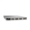
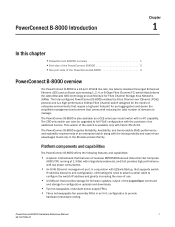
... 1, 2, 4, or 8 Gbps Fibre Channel (FC) switch that provides storage for firmware updates, output of the supportSave command and storage for Fibre Channel Storage Area Networks (SANs). Chapter PowerConnect B-8000 Introduction 1 In this chapter •PowerConnect B-8000 overview 1 •Port side of the PowerConnect B-8000 3 •Non-port side of the PowerConnect B-8000 4 PowerConnect B-8000 overview The PowerConnect B-8000 is also available as a CEE...
... 1, 2, 4, or 8 Gbps Fibre Channel (FC) switch that provides storage for firmware updates, output of the supportSave command and storage for Fibre Channel Storage Area Networks (SANs). Chapter PowerConnect B-8000 Introduction 1 In this chapter •PowerConnect B-8000 overview 1 •Port side of the PowerConnect B-8000 3 •Non-port side of the PowerConnect B-8000 4 PowerConnect B-8000 overview The PowerConnect B-8000 is also available as a CEE...
Reference Manual
Page 14
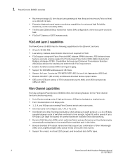
... Manual 53-1001788-01 1 PowerConnect B-8000 overview • Rack-mount design (1U form factor) using existing rail kits (fixed and mid-mount/Telco rail kits) on 8 Gbps ports. • 1, 2, 4, and 8 Gbps auto-sensing Fibre Channel switch and router ports. • Universal ports self-configure as E, F, M, or FL ports. • Inter-Switch Link (ISL) Trunking...
... Manual 53-1001788-01 1 PowerConnect B-8000 overview • Rack-mount design (1U form factor) using existing rail kits (fixed and mid-mount/Telco rail kits) on 8 Gbps ports. • 1, 2, 4, and 8 Gbps auto-sensing Fibre Channel switch and router ports. • Universal ports self-configure as E, F, M, or FL ports. • Inter-Switch Link (ISL) Trunking...
Reference Manual
Page 15
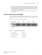
... port and LEDs, USB port, GbE ports, and Fibre Channel ports and the corresponding port status LEDs. Port side of the PowerConnect B-8000 The port side of value-added applications including Brocade Advanced Web Tools and Brocade Zoning. Figure 1 shows the port side of the... Fabric Watch, ISL Trunking, and End-to-End Performance Monitoring (APM). • Port-to-port latency minimized to 700 nanoseconds through the use of the PowerConnect B-8000 1 Switch ID pull-out tab 2 System status LED (top) System power LED (bottom) 3 Serial console port 4 Management Ethernet port 5 USB port 6 GbE ports ...
... port and LEDs, USB port, GbE ports, and Fibre Channel ports and the corresponding port status LEDs. Port side of the PowerConnect B-8000 The port side of value-added applications including Brocade Advanced Web Tools and Brocade Zoning. Figure 1 shows the port side of the... Fabric Watch, ISL Trunking, and End-to-End Performance Monitoring (APM). • Port-to-port latency minimized to 700 nanoseconds through the use of the PowerConnect B-8000 1 Switch ID pull-out tab 2 System status LED (top) System power LED (bottom) 3 Serial console port 4 Management Ethernet port 5 USB port 6 GbE ports ...
Reference Manual
Page 16
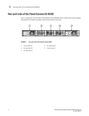
1 Non-port side of the PowerConnect B-8000 Non-port side of the PowerConnect B-8000 Figure 2 shows the non-port side of the PowerConnect B-8000, which contains the power supplies (including the AC power receptacle and AC power switch) and fans. 1 2 3 4 5 FIGURE 2 Non-port side of the PowerConnect B-8000 1 Power supply #2 2 Fan assembly #3 3 Fan assembly #2 4 Fan assembly #1 5 Power supply #1 4 PowerConnect B-8000 Hardware Reference Manual 53-1001788-01
1 Non-port side of the PowerConnect B-8000 Non-port side of the PowerConnect B-8000 Figure 2 shows the non-port side of the PowerConnect B-8000, which contains the power supplies (including the AC power receptacle and AC power switch) and fans. 1 2 3 4 5 FIGURE 2 Non-port side of the PowerConnect B-8000 1 Power supply #2 2 Fan assembly #3 3 Fan assembly #2 4 Fan assembly #1 5 Power supply #1 4 PowerConnect B-8000 Hardware Reference Manual 53-1001788-01
Reference Manual
Page 17
...-rail rack mount kit can be ordered from your switch retailer. 3. Chapter PowerConnect B-8000 Installation and Configuration 2 In this chapter •Items included with the PowerConnect B-8000 5 •Installation and safety considerations 5 •Standalone installation for a PowerConnect B-8000 7 •Cabinet installation for a PowerConnect B-8000 8 •PowerConnect B-8000 configuration 8 Items included with the PowerConnect B-8000 The following items: • Serial cable with the standard...
...-rail rack mount kit can be ordered from your switch retailer. 3. Chapter PowerConnect B-8000 Installation and Configuration 2 In this chapter •Items included with the PowerConnect B-8000 5 •Installation and safety considerations 5 •Standalone installation for a PowerConnect B-8000 7 •Cabinet installation for a PowerConnect B-8000 8 •PowerConnect B-8000 configuration 8 Items included with the PowerConnect B-8000 The following items: • Serial cable with the standard...
Reference Manual
Page 18
... a secondary connection to a branch circuit, such as an earthquake. 6 PowerConnect B-8000 Hardware Reference Manual 53-1001788-01 2 Installation and safety considerations Electrical considerations To install and operate the switch successfully, ensure the following: • The primary outlet is correctly wired,... equipment in the rack should force air in the cabinet is operating. Environmental considerations For successful installation and operation of the switch, ensure that the following cabinet requirements are met: • At a minimum, adequate cooling requires that is one rack...
... a secondary connection to a branch circuit, such as an earthquake. 6 PowerConnect B-8000 Hardware Reference Manual 53-1001788-01 2 Installation and safety considerations Electrical considerations To install and operate the switch successfully, ensure the following: • The primary outlet is correctly wired,... equipment in the rack should force air in the cabinet is operating. Environmental considerations For successful installation and operation of the switch, ensure that the following cabinet requirements are met: • At a minimum, adequate cooling requires that is one rack...
Reference Manual
Page 19
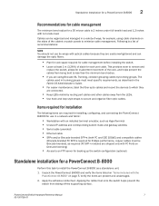
... to an FTP server for backing up the switch configuration (optional) Standalone installation for a PowerConnect B-8000 Perform this task to which they are easily overtightened and can be Brocade-branded), as a standalone unit. 1. PowerConnect B-8000 Hardware Reference Manual 7 53-1001788-01 Applying the... rubber feet onto the switch helps prevent the switch from the LEDs. • Use hook and loop style straps to minimize...
... to an FTP server for backing up the switch configuration (optional) Standalone installation for a PowerConnect B-8000 Perform this task to which they are easily overtightened and can be Brocade-branded), as a standalone unit. 1. PowerConnect B-8000 Hardware Reference Manual 7 53-1001788-01 Applying the... rubber feet onto the switch helps prevent the switch from the LEDs. • Use hook and loop style straps to minimize...
Reference Manual
Page 20
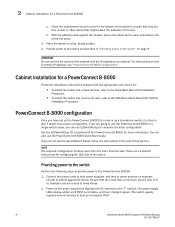
... other debris that the cords have set . Ensure that might lessen the adhesion of the switch to ensure that they are going to use the PowerConnect B-8000 in a single-switch setup, you do not want to the "I" symbol. NOTE The required configuration must be ... the power cords to both AC switches to use the PowerConnect B-8000 Quick Start Guide. The switch usually requires several minutes to the PowerConnect B-8000. 1. Providing power to the switch Perform the following steps to provide power to boot and complete POST. 8 PowerConnect B-8000 Hardware Reference Manual 53-1001788-01 ...
... other debris that the cords have set . Ensure that might lessen the adhesion of the switch to ensure that they are going to use the PowerConnect B-8000 in a single-switch setup, you do not want to the "I" symbol. NOTE The required configuration must be ... the power cords to both AC switches to use the PowerConnect B-8000 Quick Start Guide. The switch usually requires several minutes to the PowerConnect B-8000. 1. Providing power to the switch Perform the following steps to provide power to boot and complete POST. 8 PowerConnect B-8000 Hardware Reference Manual 53-1001788-01 ...
Reference Manual
Page 21
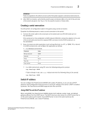
...these LEDs. Complete the following string at the prompt: tip /dev/ttya -9600 Switch IP address You can configure the PowerConnect B-8000 with a static IP address, or you can only connect to a DHCP server that the switch power and status LEDs on the left of the port side of the serial ...Stop bits Flow control 9600 8 None 1 None • In a UNIX environment using TIP, enter the following steps to create a serial connection to the switch. 1. The PowerConnect B-8000 supports both IPv4 and IPv6. The DHCP client can use a static IP address. If your DHCP server is enabled by default...
...these LEDs. Complete the following string at the prompt: tip /dev/ttya -9600 Switch IP address You can configure the PowerConnect B-8000 with a static IP address, or you can only connect to a DHCP server that the switch power and status LEDs on the left of the port side of the serial ...Stop bits Flow control 9600 8 None 1 None • In a UNIX environment using TIP, enter the following steps to create a serial connection to the switch. 1. The PowerConnect B-8000 supports both IPv4 and IPv6. The DHCP client can use a static IP address. If your DHCP server is enabled by default...
Reference Manual
Page 22
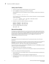
..., enter the network information in local time calculations. 10 PowerConnect B-8000 Hardware Reference Manual 53-1001788-01 Enter off Date and time settings The PowerConnect B-8000 maintains the current date and time inside a battery-backed real-time clock (RTC) circuit. If you should set them correctly. switch:admin> ipaddrset -ipv6 --add 1080::8:800:200C:417A...
..., enter the network information in local time calculations. 10 PowerConnect B-8000 Hardware Reference Manual 53-1001788-01 Enter off Date and time settings The PowerConnect B-8000 maintains the current date and time inside a battery-backed real-time clock (RTC) circuit. If you should set them correctly. switch:admin> ipaddrset -ipv6 --add 1080::8:800:200C:417A...
Reference Manual
Page 23
...mm is the year; valid values are 01 through 59. • yy is the month; switch:admin> date Fri Sep 29 17:01:48 UTC 2007 switch:admin> date "0927123007" PowerConnect B-8000 Hardware Reference Manual 11 53-1001788-01 To keep the time zone setup at least one time ...their time from the principal or primary FCS switch. PowerConnect B-8000 configuration 2 • By default, all switches in a fabric are in one external NTP server. If all switches are passed, tsclockserver sets the first obtainable address as 2000-2069). All switches in the fabric maintain the current clock server...
...mm is the year; valid values are 01 through 59. • yy is the month; switch:admin> date Fri Sep 29 17:01:48 UTC 2007 switch:admin> date "0927123007" PowerConnect B-8000 Hardware Reference Manual 11 53-1001788-01 To keep the time zone setup at least one time ...their time from the principal or primary FCS switch. PowerConnect B-8000 configuration 2 • By default, all switches in a fabric are in one external NTP server. If all switches are passed, tsclockserver sets the first obtainable address as 2000-2069). All switches in the fabric maintain the current clock server...
Reference Manual
Page 24
... Reference Manual 53-1001788-01 You are prompted to US/Central. At the prompt, select a country location. 5. 2 PowerConnect B-8000 configuration Thu Sep 27 12:30:00 UTC 2007 switch:admin> Setting time zones You must be set . The following procedure describes how to set the time zone by Country/City or by time...
... Reference Manual 53-1001788-01 You are prompted to US/Central. At the prompt, select a country location. 5. 2 PowerConnect B-8000 configuration Thu Sep 27 12:30:00 UTC 2007 switch:admin> Setting time zones You must be set . The following procedure describes how to set the time zone by Country/City or by time...
Reference Manual
Page 25
...Demand license has been purchased. ISL trunking is only available if an FC Ports on the PowerConnect B-8000 can be able to access. For more than one NTP server using a DNS name: switch:admin> tsclockserver "10.32.170.1;10.32.170.2;ntp.localdomain.net" Updating Clock Server configuration... Guide. by default, this value is LOCL, which the switch must be used as the clock server. Brocade Inter-Switch Link (ISL) Trunking Brocade ISL Trunking is optional software that allows you to all switches in the fabric. PowerConnect B-8000 configuration 2 where ntp1 is the IP address or DNS name...
...Demand license has been purchased. ISL trunking is only available if an FC Ports on the PowerConnect B-8000 can be able to access. For more than one NTP server using a DNS name: switch:admin> tsclockserver "10.32.170.1;10.32.170.2;ntp.localdomain.net" Updating Clock Server configuration... Guide. by default, this value is LOCL, which the switch must be used as the clock server. Brocade Inter-Switch Link (ISL) Trunking Brocade ISL Trunking is optional software that allows you to all switches in the fabric. PowerConnect B-8000 configuration 2 where ntp1 is the IP address or DNS name...
Reference Manual
Page 27
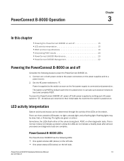
... 19 •Interpreting POST results 20 •PowerConnect B-8000 Maintenance 20 •PowerConnect B-8000 Management 22 Powering the PowerConnect B-8000 on and off both power cords to the power connectors on the power supplies and to the switch as soon as the first power supply is connected...a steady light, and a flashing light. PowerConnect B-8000 LEDs The PowerConnect B-8000 has the following steps to boot and complete POST. Connect one or both power supplies by default each AC power switch to their initial state the next time the switch is supplied to a power source 2. Power...
... 19 •Interpreting POST results 20 •PowerConnect B-8000 Maintenance 20 •PowerConnect B-8000 Management 22 Powering the PowerConnect B-8000 on and off both power cords to the power connectors on the power supplies and to the switch as soon as the first power supply is connected...a steady light, and a flashing light. PowerConnect B-8000 LEDs The PowerConnect B-8000 has the following steps to boot and complete POST. Connect one or both power supplies by default each AC power switch to their initial state the next time the switch is supplied to a power source 2. Power...
Reference Manual
Page 28
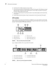
... LED 4 Ethernet link LED 5 GbE port status LED (port 0) 6 GbE port status LED (port 4) FIGURE 3 LEDs on Port Side of PowerConnect B-8000 Figure 4 shows the LEDs on the non-port side of the switch. 1 2 3 4 5 1 Power supply #2 status LED 2 Power supply #1 status LED 3 Fan assembly #3 status LED 4 Fan assembly #2 status LED ...-1001788-01 These LEDs are located in the array in each port on the non-port side of the switch LED locations Figure 3 shows the port side of the PowerConnect B-8000. Refer to the upper and lower ports in the same relative positions as the ports. • One ...
... LED 4 Ethernet link LED 5 GbE port status LED (port 0) 6 GbE port status LED (port 4) FIGURE 3 LEDs on Port Side of PowerConnect B-8000 Figure 4 shows the LEDs on the non-port side of the switch. 1 2 3 4 5 1 Power supply #2 status LED 2 Power supply #1 status LED 3 Fan assembly #3 status LED 4 Fan assembly #2 status LED ...-1001788-01 These LEDs are located in the array in each port on the non-port side of the switch LED locations Figure 3 shows the port side of the PowerConnect B-8000. Refer to the upper and lower ports in the same relative positions as the ports. • One ...


