User's Guide
Page 46
... to complete the required tasks. 6. NOTE: The following steps assume that particular command mode. When a stack is powered up enable passwords. 46 Using Dell™ OpenManage™ Switch Administrator Your switch supports up . This level is reserved for tasks that do not change the switch configuration and is presented...2. Using the CLI Command Mode Overview The CLI is required. NOTE: If you cannot use the CLI through a TCP/IP protocol network. This switch lights the Master Switch LED. During the CLI session initialization, the CLI mode is configured.
... to complete the required tasks. 6. NOTE: The following steps assume that particular command mode. When a stack is powered up enable passwords. 46 Using Dell™ OpenManage™ Switch Administrator Your switch supports up . This level is reserved for tasks that do not change the switch configuration and is presented...2. Using the CLI Command Mode Overview The CLI is required. NOTE: If you cannot use the CLI through a TCP/IP protocol network. This switch lights the Master Switch LED. During the CLI session initialization, the CLI mode is configured.

User's Guide
Page 64
The port is not linked. 64 Hardware Description The port is sending and/or receiving network traffic. Figure 4-15. Figure 4-14. SFP Port LEDs Table 4-1 contains SFP port LED definitions. Front Panel LEDs SFP Port LEDs Figure 4-15 illustrates the SFP port LEDs that indicate the status of links, power supplies, fans, system diagnostics, and the stack. Table 4-1. SFP Port LEDs Definitions LED LNK/ACT Color Solid Green Flashing Green Off Definition The port is linked. LED Definitions The front panel contains light emitting diodes (LEDs) that are above each SFP port.
The port is not linked. 64 Hardware Description The port is sending and/or receiving network traffic. Figure 4-15. Figure 4-14. SFP Port LEDs Table 4-1 contains SFP port LED definitions. Front Panel LEDs SFP Port LEDs Figure 4-15 illustrates the SFP port LEDs that indicate the status of links, power supplies, fans, system diagnostics, and the stack. Table 4-1. SFP Port LEDs Definitions LED LNK/ACT Color Solid Green Flashing Green Off Definition The port is linked. LED Definitions The front panel contains light emitting diodes (LEDs) that are above each SFP port.

User's Guide
Page 71
...a stack is described later in the stack. Configuring Dell PowerConnect 71 5 Configuring Dell PowerConnect Overview This chapter describes the initial switch configuration. You can download the release notes from the Dell Support website at support.dell.com/manuals. NOTE: Before proceeding, read the release... switch, you are installing a stack of installation and configuration procedures illustrated in Figure 5-1. Performing other procedures. This switch lights the Master Switch LED. Then, follow the order of switches, connect the terminal to use the CLI. For the ...
...a stack is described later in the stack. Configuring Dell PowerConnect 71 5 Configuring Dell PowerConnect Overview This chapter describes the initial switch configuration. You can download the release notes from the Dell Support website at support.dell.com/manuals. NOTE: Before proceeding, read the release... switch, you are installing a stack of installation and configuration procedures illustrated in Figure 5-1. Performing other procedures. This switch lights the Master Switch LED. Then, follow the order of switches, connect the terminal to use the CLI. For the ...
Getting Started Guide
Page 7
...amplifiers, power lines, and fluorescent lighting fixtures. • Ambient - The cabling is routed to avoid sources of electrical noise such as stand-alone switches. Installation This document provides basic information to install, configure, and operate Dell™ PowerConnect™ PC6224, PC6248, PC6224P, ...PC6248P, and PC6224F systems. For more information, see the User's Guide, which is available on your User Documentation CD, or check the Dell Support web site at a relative humidity...
...amplifiers, power lines, and fluorescent lighting fixtures. • Ambient - The cabling is routed to avoid sources of electrical noise such as stand-alone switches. Installation This document provides basic information to install, configure, and operate Dell™ PowerConnect™ PC6224, PC6248, PC6224P, ...PC6248P, and PC6224F systems. For more information, see the User's Guide, which is available on your User Documentation CD, or check the Dell Support web site at a relative humidity...
Getting Started Guide
Page 9
NOTE: If you will light the Master Switch LED, the top left LED in "Starting and Configuring the Switch." If you connect the terminal to a member switch, you are installing a stack of power, connect the 12 VDC power cable from a (separately purchased) PowerConnect RPS-600 for non-PoE switches or PowerConnect EPS-470 for...
NOTE: If you will light the Master Switch LED, the top left LED in "Starting and Configuring the Switch." If you connect the terminal to a member switch, you are installing a stack of power, connect the 12 VDC power cable from a (separately purchased) PowerConnect RPS-600 for non-PoE switches or PowerConnect EPS-470 for...
Getting Started Guide
Page 13
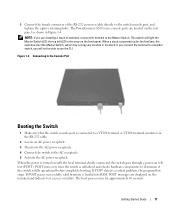
The PowerConnect 6200 series console ports are located on the terminal and indicate test success or failure. Figure 1-4. Connecting to the Console Port Booting the Switch 1 Make ... switch goes through a power-on the front panel. 3 Connect the female connector of switches, connect the terminal to the Master Switch. NOTE: If you will light the Master Switch LED, the top left LED in the array on selftest (POST). If POST detects a critical problem, the program flow stops.
The PowerConnect 6200 series console ports are located on the terminal and indicate test success or failure. Figure 1-4. Connecting to the Console Port Booting the Switch 1 Make ... switch goes through a power-on the front panel. 3 Connect the female connector of switches, connect the terminal to the Master Switch. NOTE: If you will light the Master Switch LED, the top left LED in the array on selftest (POST). If POST detects a critical problem, the program flow stops.

