Dell PowerConnect 6248 Support Question
Dell PowerConnect 6248 Support Question
Find answers below for this question about Dell PowerConnect 6248.Need a Dell PowerConnect 6248 manual? We have 5 online manuals for this item!
Question posted by Chryo on May 4th, 2014
Dell Power Connect 6248 What Does Orange Light Mean
The person who posted this question about this Dell product did not include a detailed explanation. Please use the "Request More Information" button to the right if more details would help you to answer this question.
Current Answers
Related Dell PowerConnect 6248 Manual Pages
Command Line Interface Guide - Page 630
...-request/identity frame to 3600 seconds. The feature accepts a VLAN name as an alternative to display 802.1X status for the switch or for a supplicant. Syntax show dot1x ethernet 1/g8
Administrative Mode Disabled
630
802.1x Commands A valid Ethernet interface.
Example ...(config-if-1/g16)# dot1x timeout tx-period 3600
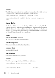
show dot1x
Use the show dot1x command in Power Connect Release 2.1.
Command Line Interface Guide - Page 635
The username representing the identity of time, in Power Connect Release 2.1. If the port is Authorized, it shows the last user that was authenticated on the RADIUS server and client.
The VLAN assigned to 0. show ...
Command Line Interface Guide - Page 1314

....16.1.1 23
2
172.16.1.2
172.16.1.2 23
The following example displays a list of open telnet sessions to which the switch is connected through a Telnet session IP address of the remote host Telnet TCP port number
1314
System Management Commands Command Mode Privileged EXEC mode
User Guidelines This ...
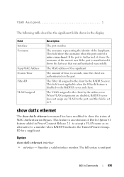
User's Guide - Page 5
Power Connection 53
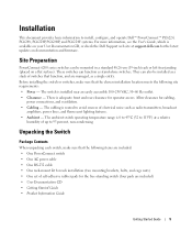
4 Hardware Description
Overview 55 Front Panel 56 Rear Panel 59 Console (RS-232) Port 61 Physical Dimensions 61 Power Supplies ... 68
5 Configuring Dell PowerConnect
Overview 71 Starting the CLI 72 General Configuration Information 74
Terminal Connection Configuration 74 Baud Rate 74 Other Configuration Requirements 74 Booting the Switch 75 Configuration Overview ...
User's Guide - Page 38
...It describes the advantages of abstracting an encrypted connection between two stations.
Once established, such a connection is a client/server-based protocol in a typical network.
TACACS+
TACACS+ provides centralized security for the PowerConnect PowerConnect 6200 Series switches are available on the Dell Support website at www.support.dell.com/manuals: • Getting Started Guide...
User's Guide - Page 46
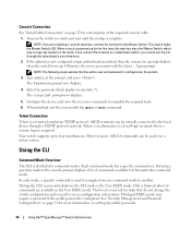
This switch lights the Master Switch LED.
The console# prompt now displays.
5. In each mode, a specific command is a terminal emulation TCP/IP protocol. This level is reserved for tasks that the admin user and password is powered up enable passwords.
46
Using Dell™ OpenManage™ Switch Administrator When a stack is configured on the system. 3. NOTE: The...
User's Guide - Page 49
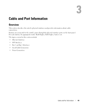
...-Duplex, Full-Duplex, Auto) is set. Stations are connected to the switch's ports through the physical interface ports on the front panel. The topics covered in this section include: • Ethernet Interface • SFP Interfaces • Bay 1 and Bay 2 Interfaces • Serial Cable Connection • Power Connection
Cable and Port Information
49 3
Cable and Port...
User's Guide - Page 53
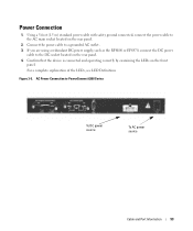
... on the rear panel.
2. AC Power Connection to the DC socket located on the rear panel. 4. If you are using a redundant DC power supply, such as the RPS600 or EPS470, connect the DC power
cable to PowerConnect 6200 Series
To DC power source
To AC power source
Cable and Port Information
53 Connect the power cable to the AC main...
User's Guide - Page 63
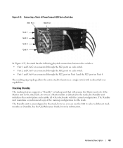
...PowerConnect 6200 Series Switches
XG1 Port
XG2 Port
Unit 1 Unit 2 Unit 3 Unit 4
In Figure 4-13, the stack has the following physical connections between the switches: • Unit 1 and Unit 2 are connected through the XG1 ports on each switch. • Unit 2 and Unit 3 are connected through the XG2 ports on each switch. • Unit 1 and Unit 4 are connected... a single switch with the current...
User's Guide - Page 71

... the release notes from the Dell Support website at support.dell.com/manuals. This switch lights the Master Switch LED. For the initial configuration, perform the standard switch configuration. Configuring Dell PowerConnect
71 5
Configuring Dell PowerConnect
Overview
This chapter describes the initial switch configuration. If you connect the terminal to a subordinate switch, you are installing...
User's Guide - Page 426

...Repeat Count - Specifies local device's MED Classification. Figure 7-99. The range is typically a LAN Switch/Router, IEEE 802.1 Bridge, IEEE 802.11 Wireless Access Point, and so on. Modifying the .... There are saved to 10). The fourth device is Network Connectivity Device, which is from (1 to the switch.
Configuring LLDP-MED Global Settings with CLI Commands For information about...
User's Guide - Page 765

... this menu page:
Configuring IP Multicast
765 In such cases, PIM-SM provides a means to switch to build a shared distribution tree, as is encapsulated in place of query message....an existing Unicast routing table and a Join/Prune/Graft mechanism to shutoff duplicate flows on the switch at a time. Assert messages are used to efficiently route multicast traffic to -
To display the...
Getting Started Guide - Page 7
... 45ºC (32 to 113ºF) at support.dell.com for the free-standing switch (four pads are managed, as radio transmitters, broadcast
amplifiers, power lines, and fluorescent lighting fixtures. • Ambient - Allow clearance for operator access. There is adequate front and rear clearance for cabling,
power connections, and ventilation. • Cabling - The cabling is routed...
Getting Started Guide - Page 9
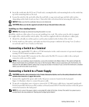
... at the other switches that connect to or support the switch. 1 Connect the supplied AC power cable to the serial connector of power, connect the 12 VDC power cable from a (separately purchased) PowerConnect RPS-600 for non-PoE switches or PowerConnect EPS-470 for PoE switches to the Master Switch. Getting Started Guide
7
Connecting a Switch to a Terminal
1 Connect the supplied RS...
Getting Started Guide - Page 12

... that you need to assemble and cable the stack before powering up and configuring the stack.
1 Connect an RS-232 crossover cable to www.microsoft.com for this...Dell Support website at support.dell.com. d Set the flow control to configure the switch or stack.
You can download the release notes from the Dell Support website at support.dell.com. Connecting the Terminal to the switch...
Getting Started Guide - Page 13
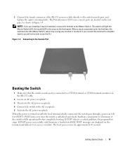
...
2 Locate an AC power receptacle.
3 Deactivate the AC power receptacle.
4 Connect the switch to the AC receptacle.
5 Activate the AC power receptacle. The PowerConnect 6200 series console ports are displayed on selftest (POST). Getting Started Guide
11 3 Connect the female connector of switches, connect the terminal to the Master Switch. NOTE: If you will light the Master Switch LED, the...
Getting Started Guide - Page 37
...
• 启用 SNMPv1/2c SNMPv3
admin SNMP、HTTP 及 CLI 界面。
0.0.0.0) IP IP VLAN (1) 配置 IP
Enter
Dell POST Welcome to manually configure the switch. You must respond to the next question to run the setup wizard within 60 seconds 60 Y/N y(是)
35 Note: You...
Getting Started Guide - Page 266

...port counters show stack-port diag show switch
show supported switchtype
LED
LED Dell Power Connect PC6248P ,PC6224P ,PC6248 , PC6224ו.PC6224F -
PowerConnect 6200
PC 6224
1-1
PC 6248
2-1
...
Release Notes - Page 5
... Banner
The system supports a configurable message of the switch will function according to download files via an HTTP session...power failure, hardware failure, or software fault on the console. PowerConnect 6224/6224F/6224P/6248/6248P Release Notes
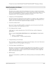
Added Functionality in this Release ¾ Non-Stop Forwarding
This feature creates an option to allow the stacking and CX-4 plug-in Power Connect...
Configuration Guide - Page 25
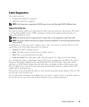
The switch uses Time Domain Reflectometry (TDR) technology to determine the quality and characteristics of the test. The cable may in fact be determined. The...has an active link while the cable test is run, the link can go down and a cable is attached to determine the cable connection status on the specified port. NOTE: The cable test feature is supported by the PHY for copper cable.


