
Command Line Interface Guide
Page 1330
System Description: Dell Ethernet Switch System Up Time: 0 days, 00h:02m:14s System Contact: System Name: System Location: Burned In MAC Address: 00FF.F2A3.8888 System Object ID: 1.3.6.1.4.1.674.10895.3011 System Model ID: PCT6248 Machine Type: Dell 48 Port Gigabit Ethernet Temperature Sensors: Unit ---- 1 Temperature (Celsius 25 Status -----OK Fans: Unit ---- 1 1 1 Description ----------Fan 1 Fan 2 Fan 3 Status -----OK OK OK 1 Fan 4 OK 1330 System Management Commands
System Description: Dell Ethernet Switch System Up Time: 0 days, 00h:02m:14s System Contact: System Name: System Location: Burned In MAC Address: 00FF.F2A3.8888 System Object ID: 1.3.6.1.4.1.674.10895.3011 System Model ID: PCT6248 Machine Type: Dell 48 Port Gigabit Ethernet Temperature Sensors: Unit ---- 1 Temperature (Celsius 25 Status -----OK Fans: Unit ---- 1 1 1 Description ----------Fan 1 Fan 2 Fan 3 Status -----OK OK OK 1 Fan 4 OK 1330 System Management Commands
User's Guide
Page 62
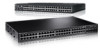
...next switch. 3. See Figure 4-13. 1. The PowerConnect 6248 has four fans. If necessary, use a separately purchased, long (3 meter) stacking cable to stacking port two on page 67 for information. For PoE switches, you can stack up to 12 PowerConnect 6224 and/or 6248 switches, supporting up to 576 ... the remaining stacking cable to connect the remaining free ports, one on the switch to connect the switches. Ventilation System Three fans cool the PowerConnect 6224. Power Supplies The 6200 series switches have one of the short stacking cables into either of the stacking ports of the top...
...next switch. 3. See Figure 4-13. 1. The PowerConnect 6248 has four fans. If necessary, use a separately purchased, long (3 meter) stacking cable to stacking port two on page 67 for information. For PoE switches, you can stack up to 12 PowerConnect 6224 and/or 6248 switches, supporting up to 576 ... the remaining stacking cable to connect the remaining free ports, one on the switch to connect the switches. Ventilation System Three fans cool the PowerConnect 6224. Power Supplies The 6200 series switches have one of the short stacking cables into either of the stacking ports of the top...

User's Guide
Page 64
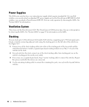
Figure 4-14. SFP Port LEDs Table 4-1 contains SFP port LED definitions. The port is linked. Figure 4-15. Front Panel LEDs SFP Port LEDs Figure 4-15 illustrates the SFP port LEDs that indicate the status of links, power supplies, fans, system diagnostics, and the stack. Table 4-1. LED Definitions The front panel contains light emitting diodes (LEDs) that are above each SFP port. SFP Port LEDs Definitions LED LNK/ACT Color Solid Green Flashing Green Off Definition The port is sending and/or receiving network traffic. The port is not linked. 64 Hardware Description
Figure 4-14. SFP Port LEDs Table 4-1 contains SFP port LED definitions. The port is linked. Figure 4-15. Front Panel LEDs SFP Port LEDs Figure 4-15 illustrates the SFP port LEDs that indicate the status of links, power supplies, fans, system diagnostics, and the stack. Table 4-1. LED Definitions The front panel contains light emitting diodes (LEDs) that are above each SFP port. SFP Port LEDs Definitions LED LNK/ACT Color Solid Green Flashing Green Off Definition The port is sending and/or receiving network traffic. The port is not linked. 64 Hardware Description
User's Guide
Page 67
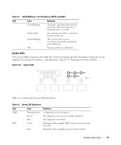
.... Hardware Description 67 Amber Solid An overload or short has occurred on the right side of the front panel, provide information about the power supplies, fans, thermal conditions, and diagnostics. The PoE powered device is being detected, or is present and operating correctly. Figure 4-17. The diagnostics test was successfully completed...
.... Hardware Description 67 Amber Solid An overload or short has occurred on the right side of the front panel, provide information about the power supplies, fans, thermal conditions, and diagnostics. The PoE powered device is being detected, or is present and operating correctly. Figure 4-17. The diagnostics test was successfully completed...
User's Guide
Page 68
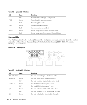
...status of the switch in the stack. Figure 4-18 illustrates the Stacking LEDs. The unit is not present. System LED Definitions LED PWR FAN Temp Color Off Green Red Green Red Green Red Definition Redundant Power Supply is the 2nd or 8th switch in the stack. Stacking LED...stack. The stack ID is operating as a standalone switch. System temperature is the Master Switch in the range of 7 to 6. Fans are operating correctly. One or more fans have failed. System temperature has exceeded threshold limit. The unit is below threshold limit. The unit is in the stack. Table ...
...status of the switch in the stack. Figure 4-18 illustrates the Stacking LEDs. The unit is not present. System LED Definitions LED PWR FAN Temp Color Off Green Red Green Red Green Red Definition Redundant Power Supply is the 2nd or 8th switch in the stack. Stacking LED...stack. The stack ID is operating as a standalone switch. System temperature is the Master Switch in the range of 7 to 6. Fans are operating correctly. One or more fans have failed. System temperature has exceeded threshold limit. The unit is below threshold limit. The unit is in the stack. Table ...
User's Guide
Page 119
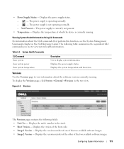
... which the device is currently not present. • Temperature - Table 6-2. Displays the unit's number in the tree view. Not Present - Displays the system temperature and fan status. Displays the version number of the other of the boot code. • Image1 Version - • Power Supply Status - The power supply is currently running...
... which the device is currently not present. • Temperature - Table 6-2. Displays the unit's number in the tree view. Not Present - Displays the system temperature and fan status. Displays the version number of the other of the boot code. • Image1 Version - • Power Supply Status - The power supply is currently running...
Getting Started Guide
Page 22
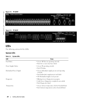
... Power Supply Status Redundant Power Supply Diagnostic Temperature State • Green: All Fans are operating correctly • Red: One or more fans have failed • Green: PS operating correctly • Red: PS failure • Green: Redundant supply present and operating correctly • Red: Redundant supply present...temperature is below threshold limit • Red: System temperature is above threshold limit 20 Getting Started Guide PC 6248P Figure 1-5. Systems LEDs Table 1-1. www.dell.com | support.dell.com Figure 1-4. PC 6224F LEDs The following sections list the LEDs.
... Power Supply Status Redundant Power Supply Diagnostic Temperature State • Green: All Fans are operating correctly • Red: One or more fans have failed • Green: PS operating correctly • Red: PS failure • Green: Redundant supply present and operating correctly • Red: Redundant supply present...temperature is below threshold limit • Red: System temperature is above threshold limit 20 Getting Started Guide PC 6248P Figure 1-5. Systems LEDs Table 1-1. www.dell.com | support.dell.com Figure 1-4. PC 6224F LEDs The following sections list the LEDs.

