User's Guide
Page 38
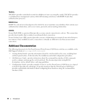
... authentication information, such as user name, password, and accounting information. TACACS+ TACACS+ provides centralized security for the PowerConnect PowerConnect 6200 Series switches are available on the Dell Support website at www.support.dell.com/manuals: • Getting Started Guide-provides information about configuring those functions using the command line interface (CLI). 38 Introduction SSH/SSL Secure Shell...
... authentication information, such as user name, password, and accounting information. TACACS+ TACACS+ provides centralized security for the PowerConnect PowerConnect 6200 Series switches are available on the Dell Support website at www.support.dell.com/manuals: • Getting Started Guide-provides information about configuring those functions using the command line interface (CLI). 38 Introduction SSH/SSL Secure Shell...
Getting Started Guide
Page 7
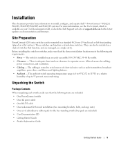
... or switches, make sure that function, and are included) • User Documentation CD • Getting Started Guide • Product Information Guide Getting Started Guide 5 Allow clearance for the latest updates on documentation and firmware. The cabling is routed to 95 percent... - Installation This document provides basic information to install, configure, and operate Dell™ PowerConnect™ PC6224, PC6248, PC6224P, PC6248P, and PC6224F systems. For more information, see the User's Guide, which is adequate front and rear clearance for operator access. Unpacking the ...
... or switches, make sure that function, and are included) • User Documentation CD • Getting Started Guide • Product Information Guide Getting Started Guide 5 Allow clearance for the latest updates on documentation and firmware. The cabling is routed to 95 percent... - Installation This document provides basic information to install, configure, and operate Dell™ PowerConnect™ PC6224, PC6248, PC6224P, PC6248P, and PC6224F systems. For more information, see the User's Guide, which is adequate front and rear clearance for operator access. Unpacking the ...
Getting Started Guide
Page 8
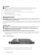
.... 4 Remove all cables from the bottom up to the mounting holes in the Product Information Guide as well as the PowerConnect RPS-600 for non-PoE switches or the PowerConnect EPS-470 for the rack-mounting bracket on one side of the switch. Figure 1-1. Installing in...www.dell.com | support.dell.com Unpacking Steps NOTE: Before unpacking the switch, inspect the container and immediately report any evidence of the switch, if they have been attached. CAUTION: Disconnect all packing material. 5 Inspect the product and accessories for other side of the switch. 6 Getting Started Guide We...
.... 4 Remove all cables from the bottom up to the mounting holes in the Product Information Guide as well as the PowerConnect RPS-600 for non-PoE switches or the PowerConnect EPS-470 for the rack-mounting bracket on one side of the switch. Figure 1-1. Installing in...www.dell.com | support.dell.com Unpacking Steps NOTE: Before unpacking the switch, inspect the container and immediately report any evidence of the switch, if they have been attached. CAUTION: Disconnect all packing material. 5 Inspect the product and accessories for other side of the switch. 6 Getting Started Guide We...
Getting Started Guide
Page 9
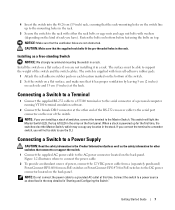
... well as the safety information for the first time, the switches elect the Master Switch, which may occupy any location in the stack. Getting Started Guide 7 CAUTION: Make sure that the ventilation holes are not obstructed. Installing as described in the step detailed in the array on the front ... the power cable. 2 To provide a redundant source of power, connect the 12 VDC power cable from a (separately purchased) PowerConnect RPS-600 for non-PoE switches or PowerConnect EPS-470 for PoE switches to the DC power connector located on top. NOTE: Do not connect the power cable to a ...
... well as the safety information for the first time, the switches elect the Master Switch, which may occupy any location in the stack. Getting Started Guide 7 CAUTION: Make sure that the ventilation holes are not obstructed. Installing as described in the step detailed in the array on the front ... the power cable. 2 To provide a redundant source of power, connect the 12 VDC power cable from a (separately purchased) PowerConnect RPS-600 for non-PoE switches or PowerConnect EPS-470 for PoE switches to the DC power connector located on top. NOTE: Do not connect the power cable to a ...
Getting Started Guide
Page 10
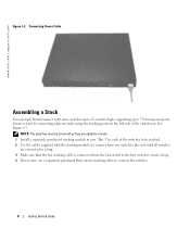
....dell.com | support.dell.com Figure 1-2. Create a stack by connecting adjacent units using the stacking ports on the left side of the switches to be turned off as they are connected in each of the switch rear. Connecting Power Cable Assembling a Stack You can stack PowerConnect ...6200 series switches up to 12 switches high, supporting up to connect the switches. 8 Getting Started Guide NOTE: The switches must be stacked. 2 Use the cables supplied with the stacking modules ...
....dell.com | support.dell.com Figure 1-2. Create a stack by connecting adjacent units using the stacking ports on the left side of the switches to be turned off as they are connected in each of the switch rear. Connecting Power Cable Assembling a Stack You can stack PowerConnect ...6200 series switches up to 12 switches high, supporting up to connect the switches. 8 Getting Started Guide NOTE: The switches must be stacked. 2 Use the cables supplied with the stacking modules ...
Getting Started Guide
Page 11
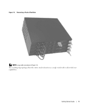
Connecting a Stack of Switches NOTE: Long cable not shown in Figure 1-3. The resulting ring topology allows the entire stack to function as a single switch with resilient fail-over capabilities. Figure 1-3. Getting Started Guide 9
Connecting a Stack of Switches NOTE: Long cable not shown in Figure 1-3. The resulting ring topology allows the entire stack to function as a single switch with resilient fail-over capabilities. Figure 1-3. Getting Started Guide 9

Getting Started Guide
Page 12
...keys. c Set the data format to none. With Windows 2000 Service Pack 2, the arrow keys function properly in the User's Guide located on your User Documentation CD. Connecting the Terminal to the Switch To monitor and configure the switch via serial console, use ... as a data terminal equipment (DTE) connector. Go to configure the switch or stack. www.dell.com | support.dell.com Starting and Configuring the Switch After completing all external connections, connect a terminal to a switch to www.microsoft.com for more information on Windows 2000 service packs. 10 Getting Started Guide
...keys. c Set the data format to none. With Windows 2000 Service Pack 2, the arrow keys function properly in the User's Guide located on your User Documentation CD. Connecting the Terminal to the Switch To monitor and configure the switch via serial console, use ... as a data terminal equipment (DTE) connector. Go to configure the switch or stack. www.dell.com | support.dell.com Starting and Configuring the Switch After completing all external connections, connect a terminal to a switch to www.microsoft.com for more information on Windows 2000 service packs. 10 Getting Started Guide
Getting Started Guide
Page 13
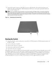
Figure 1-4. Getting Started Guide 11 This switch will not be able to use the CLI. If POST detects a critical problem, the program flow stops. When a stack is powered up ... a member switch, you are located on the terminal and indicate test success or failure. POST runs every time the switch is loaded into RAM. The PowerConnect 6200 series console ports are installing a stack of the RS-232 crossover cable directly to the AC receptacle. 5 Activate the AC power receptacle.
Figure 1-4. Getting Started Guide 11 This switch will not be able to use the CLI. If POST detects a critical problem, the program flow stops. When a stack is powered up ... a member switch, you are located on the terminal and indicate test success or failure. POST runs every time the switch is loaded into RAM. The PowerConnect 6200 series console ports are installing a stack of the RS-232 crossover cable directly to the AC receptacle. 5 Activate the AC power receptacle.
Getting Started Guide
Page 14
...used by the SNMP manager at any point by using the Dell Easy Setup Wizard, or by entering [ctrl+z], but all IP addresses. • Configures the default gateway IP address. 12 Getting Started Guide The wizard sets up the SNMP community string to the ...password. The wizard configures one privileged user account during the initial configuration. After the initial configuration, you received it. • The PowerConnect switch booted successfully. • The console connection was never configured before and is not configured with a valid password. Initial Configuration ...
...used by the SNMP manager at any point by using the Dell Easy Setup Wizard, or by entering [ctrl+z], but all IP addresses. • Configures the default gateway IP address. 12 Getting Started Guide The wizard sets up the SNMP community string to the ...password. The wizard configures one privileged user account during the initial configuration. After the initial configuration, you received it. • The PowerConnect switch booted successfully. • The console connection was never configured before and is not configured with a valid password. Initial Configuration ...
Getting Started Guide
Page 15
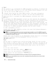
...is enabled and the community string is set up as defined. • A network management system is set up and running an example Dell Easy Setup Wizard session, using the default system configuration. NOTE: In the example below, the possible user options are used is booted, ...within 60 seconds)? [Y/N] y Getting Started Guide 13 The following dialog appears: Welcome to manually configure the switch. Note: You can skip the setup wizard, and enter CLI mode to Dell Easy Setup Wizard The setup wizard guides you through the initial switch configuration, and gets you can access the SNMP,...
...is enabled and the community string is set up as defined. • A network management system is set up and running an example Dell Easy Setup Wizard session, using the default system configuration. NOTE: In the example below, the possible user options are used is booted, ...within 60 seconds)? [Y/N] y Getting Started Guide 13 The following dialog appears: Welcome to manually configure the switch. Note: You can skip the setup wizard, and enter CLI mode to Dell Easy Setup Wizard The setup wizard guides you through the initial switch configuration, and gets you can access the SNMP,...
Getting Started Guide
Page 16
... the switch using SNMP (required for more information on setting up an SNMP version 3 account, see the User's Guide. For more information on adding management systems, see the User's Guide. engine ID, view, etc.). NOTE: You can use Dell Open Manage Network Manager or other accounts and change this account. See the User... Management System (A.B.C.D) or wildcard (0.0.0.0) to manage from any Management Station {0.0.0.0}: 192.168.1.10 Step 2: Now we need to access the switch. For more information. 14 Getting Started Guide
... the switch using SNMP (required for more information on setting up an SNMP version 3 account, see the User's Guide. For more information on adding management systems, see the User's Guide. engine ID, view, etc.). NOTE: You can use Dell Open Manage Network Manager or other accounts and change this account. See the User... Management System (A.B.C.D) or wildcard (0.0.0.0) to manage from any Management Station {0.0.0.0}: 192.168.1.10 Step 2: Now we need to access the switch. For more information. 14 Getting Started Guide
Getting Started Guide
Page 17
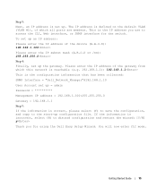
... (Y) to save the configuration, and copy to access the CLI, Web interface, or SNMP interface for using the Dell Easy Setup Wizard. Please enter the IP address of the gateway from which this network is reachable (e.g. 192.168...members. The IP address is incorrect, select (N) to discard configuration and restart the wizard: [Y/N] y Thank you use to the start-up configuration file. To set up = admin Password Management IP address = 192.168.1.100:255.255.255.0 Gateway = 192.168...up. You will now enter CLI mode. Step 3: Next, an IP address is set up the gateway. Getting Started Guide 15
... (Y) to save the configuration, and copy to access the CLI, Web interface, or SNMP interface for using the Dell Easy Setup Wizard. Please enter the IP address of the gateway from which this network is reachable (e.g. 192.168...members. The IP address is incorrect, select (N) to discard configuration and restart the wizard: [Y/N] y Thank you use to the start-up configuration file. To set up = admin Password Management IP address = 192.168.1.100:255.255.255.0 Gateway = 192.168...up. You will now enter CLI mode. Step 3: Next, an IP address is set up the gateway. Getting Started Guide 15
Getting Started Guide
Page 18
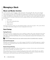
www.dell.com | support.dell.com Managing a Stack Master and Member Switches A stack of the ...You can be managed as the Suspended Stacking Mode. You can then synchronize the firmware on the Master Switch. 16 Getting Started Guide When a stack is assigned a Stack ID. The system will not become valid for operation. Once Stack ID ...Version, Management Preference, Switch MAC Address, and Switch Serial Number. See the CLI Reference Manual and the User's Guide for the stack. Firmware Version Checking Following Stack ID assignment, the Master Switch performs a consistency check to view ...
www.dell.com | support.dell.com Managing a Stack Master and Member Switches A stack of the ...You can be managed as the Suspended Stacking Mode. You can then synchronize the firmware on the Master Switch. 16 Getting Started Guide When a stack is assigned a Stack ID. The system will not become valid for operation. Once Stack ID ...Version, Management Preference, Switch MAC Address, and Switch Serial Number. See the CLI Reference Manual and the User's Guide for the stack. Firmware Version Checking Following Stack ID assignment, the Master Switch performs a consistency check to view ...
Getting Started Guide
Page 19
... saved for Suspended Stacking Mode After system initialization is stored in the Master Switch to a member switch. If a stacking partner is taking that Stack ID. Getting Started Guide 17 The entire network may be assigned a Stack ID that has not already been assigned to another switch in the stack. If the Master Switch...
... saved for Suspended Stacking Mode After system initialization is stored in the Master Switch to a member switch. If a stacking partner is taking that Stack ID. Getting Started Guide 17 The entire network may be assigned a Stack ID that has not already been assigned to another switch in the stack. If the Master Switch...
Getting Started Guide
Page 20
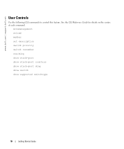
See the CLI Reference Guide for details on the syntax of each command. movemanagement reload member set description switch priority switch renumber stacking show stack-port show stack-port counters show stack-port diag show switch show supported switchtype 18 Getting Started Guide www.dell.com | support.dell.com User Controls Use the following CLI commands to control this feature.
See the CLI Reference Guide for details on the syntax of each command. movemanagement reload member set description switch priority switch renumber stacking show stack-port show stack-port counters show stack-port diag show switch show supported switchtype 18 Getting Started Guide www.dell.com | support.dell.com User Controls Use the following CLI commands to control this feature.
Getting Started Guide
Page 21
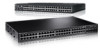
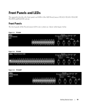
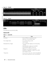
PC 6224 Figure 1-2. PC 6248 Figure 1-3. PC 6224P Getting Started Guide 19 Figure 1-1. Front Panels and LEDs This appendix describes the front panels and LEDs of the Dell PowerConnect PC6224, PC6248, PC6224P, PC6248P, and PC6224F systems. Front Panels The front panels of the PowerConnect 6200 series systems are shown in the figures below.
PC 6224 Figure 1-2. PC 6248 Figure 1-3. PC 6224P Getting Started Guide 19 Figure 1-1. Front Panels and LEDs This appendix describes the front panels and LEDs of the Dell PowerConnect PC6224, PC6248, PC6224P, PC6248P, and PC6224F systems. Front Panels The front panels of the PowerConnect 6200 series systems are shown in the figures below.
Getting Started Guide
Page 22
... Green: Diagnostics completed successfully • Red: Diagnostics failed • Green: System temperature is below threshold limit • Red: System temperature is above threshold limit 20 Getting Started Guide PC 6224F LEDs The following sections list the LEDs. www.dell.com | support.dell.com Figure 1-4. PC 6248P Figure 1-5. Systems LEDs Table 1-1.
... Green: Diagnostics completed successfully • Red: Diagnostics failed • Green: System temperature is below threshold limit • Red: System temperature is above threshold limit 20 Getting Started Guide PC 6224F LEDs The following sections list the LEDs. www.dell.com | support.dell.com Figure 1-4. PC 6248P Figure 1-5. Systems LEDs Table 1-1.
Getting Started Guide
Page 23
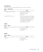
SFP LED LED Single color: State • Green Solid: Link • Green Blinking: Activity • Off: No Link Getting Started Guide 21 RJ-45 LEDs (PoE) The RJ-45 ports will have two integrated LEDs (One bi-color and one single color). Dual color: State • ...
SFP LED LED Single color: State • Green Solid: Link • Green Blinking: Activity • Off: No Link Getting Started Guide 21 RJ-45 LEDs (PoE) The RJ-45 ports will have two integrated LEDs (One bi-color and one single color). Dual color: State • ...
Configuration Guide
Page 10
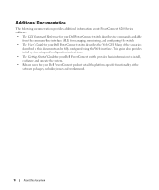
... this document can be fully configured using the Web interface. This guide also provides initial system setup and configuration instructions. • The Getting Started Guide for your Dell PowerConnect switch provides basic information to install, configure, and operate the system. • Release notes for your Dell PowerConnect product detail the platform-specific functionality of the scenarios described in...
... this document can be fully configured using the Web interface. This guide also provides initial system setup and configuration instructions. • The Getting Started Guide for your Dell PowerConnect switch provides basic information to install, configure, and operate the system. • Release notes for your Dell PowerConnect product detail the platform-specific functionality of the scenarios described in...
Configuration Guide
Page 11
System Configuration 11 2 System Configuration This section provides configuration scenarios for the following features: • "Traceroute" on page 12 • "Configuration Scripting" on page 13 • "Outbound Telnet" on page 16 • "Simple Network Time Protocol (SNTP)" on page 17 • "Syslog" on page 20 • "Port Description" on page 22 • "Storm Control" on page 23 • "Cable Diagnostics" on page 25 NOTE: For information on setting up the hardware and serial or TFTP connection, refer to the Getting Started Guide for your system.
System Configuration 11 2 System Configuration This section provides configuration scenarios for the following features: • "Traceroute" on page 12 • "Configuration Scripting" on page 13 • "Outbound Telnet" on page 16 • "Simple Network Time Protocol (SNTP)" on page 17 • "Syslog" on page 20 • "Port Description" on page 22 • "Storm Control" on page 23 • "Cable Diagnostics" on page 25 NOTE: For information on setting up the hardware and serial or TFTP connection, refer to the Getting Started Guide for your system.


