
Command Line Interface Guide
Page 198
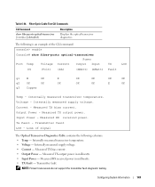
... - Loss of signal 198 PHY Diagnostics Commands www.dell.com | support.dell.com Examples The following example displays the optical transceiver diagnostics. Input LOS Power ------ --- Internally measured supply voltage. Output Power - E OK OK OK OK OK OK OK Temp - Measured TX bias current. Output Power ------ Measured RX received power. console# show fiber-ports optical-transceiver Port Temp...
... - Loss of signal 198 PHY Diagnostics Commands www.dell.com | support.dell.com Examples The following example displays the optical transceiver diagnostics. Input LOS Power ------ --- Internally measured supply voltage. Output Power - E OK OK OK OK OK OK OK Temp - Measured TX bias current. Output Power ------ Measured RX received power. console# show fiber-ports optical-transceiver Port Temp...
Command Line Interface Guide
Page 199
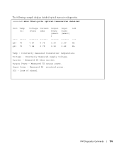
... output power. Internally measured supply voltage. Input Power - Loss of signal PHY Diagnostics Commands 199 Measured TX bias current. LOS - Measured RX received power. Current - Output Power - Voltage - The following example displays detailed optical transceiver diagnostics. console# show fiber-ports optical-transceiver detailed Port Temp [C] ---- ----g23 70 g21 70 Voltage [Volt] Current [mA] Output Power [mWatt...
... output power. Internally measured supply voltage. Input Power - Loss of signal PHY Diagnostics Commands 199 Measured TX bias current. LOS - Measured RX received power. Current - Output Power - Voltage - The following example displays detailed optical transceiver diagnostics. console# show fiber-ports optical-transceiver detailed Port Temp [C] ---- ----g23 70 g21 70 Voltage [Volt] Current [mA] Output Power [mWatt...
Command Line Interface Guide
Page 324
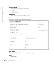
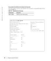
...(days,hour:min:sec): System Contact: System Name: System location: System MAC Address: Sys Object ID: Type: PowerConnect 5324 Corporate 1,22:38:21 RS1 00:10:B5:F4:00:01 Power Supply -----------Main Secondary Status OK OK Fan -----------1 2 Status OK OK show version The show version 324 System Management Command Mode.... Example The following example displays the system information. Syntax show version User EXEC mode command displays the system version information. www.dell.com | support.dell.com Default Configuration This command has no user guidelines for this command.
...(days,hour:min:sec): System Contact: System Name: System location: System MAC Address: Sys Object ID: Type: PowerConnect 5324 Corporate 1,22:38:21 RS1 00:10:B5:F4:00:01 Power Supply -----------Main Secondary Status OK OK Fan -----------1 2 Status OK OK show version The show version 324 System Management Command Mode.... Example The following example displays the system information. Syntax show version User EXEC mode command displays the system version information. www.dell.com | support.dell.com Default Configuration This command has no user guidelines for this command.
User's Guide
Page 4
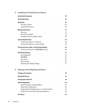
3 Installing the PowerConnect Device Installation Precautions 35 Site Requirements 36 Unpacking 36 Package Contents 36 Unpacking the Device 36 Mounting the Device 37 Overview 37 Mounting the System 37 Installing the Device without a Rack 38 Connecting the Device 38 Connecting a Device to a Terminal 38 Connecting a Device to a Power Supply 39 Port Connections, Cables, and...
3 Installing the PowerConnect Device Installation Precautions 35 Site Requirements 36 Unpacking 36 Package Contents 36 Unpacking the Device 36 Mounting the Device 37 Overview 37 Mounting the System 37 Installing the Device without a Rack 38 Connecting the Device 38 Connecting a Device to a Terminal 38 Connecting a Device to a Power Supply 39 Port Connections, Cables, and...
User's Guide
Page 30
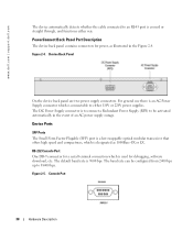
... 30 Hardware Description The default baud rate is crossed or straight through, and functions either 110V or 220V power supplies. www.dell.com | support.dell.com The device automatically detects whether the cable connected to an RJ-45 port is 9600 bps. Device Ports...or LX. Figure 2-4. For general use there is an AC Power Supply connector which is designated as illustrated in the event of an AC power supply outage. The DC Power Supply connector is connectable to 38400 bps. Figure 2-5. PowerConnect Back Panel Port Description The device back panel contains connectors for ...
... 30 Hardware Description The default baud rate is crossed or straight through, and functions either 110V or 220V power supplies. www.dell.com | support.dell.com The device automatically detects whether the cable connected to an RJ-45 port is 9600 bps. Device Ports...or LX. Figure 2-4. For general use there is an AC Power Supply connector which is designated as illustrated in the event of an AC power supply outage. The DC Power Supply connector is connectable to 38400 bps. Figure 2-5. PowerConnect Back Panel Port Description The device back panel contains connectors for ...
User's Guide
Page 31
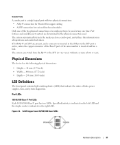
....32 inch) • Depth - 255 mm (10.03 inch) LED Definitions The front panel contains light emitting diodes (LED) that indicate the status of links, power supplies, fans, and system diagnostics. Speed/link/activity is indicated on the left LED and the duplex mode is inserted and has a link. Port features and...
....32 inch) • Depth - 255 mm (10.03 inch) LED Definitions The front panel contains light emitting diodes (LED) that indicate the status of links, power supplies, fans, and system diagnostics. Speed/link/activity is indicated on the left LED and the duplex mode is inserted and has a link. Port features and...

User's Guide
Page 32
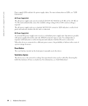
When the SFP port is connected, the Duplex LED on the left side of the front panel, provide information about the power supplies, fans, thermal conditions, and diagnostics. www.dell.com | support.dell.com The RJ-45 LED indications are described in the following table: Table 2-1. The port is Green. Figure 2-8 illustrates the system LEDs...
When the SFP port is connected, the Duplex LED on the left side of the front panel, provide information about the power supplies, fans, thermal conditions, and diagnostics. www.dell.com | support.dell.com The RJ-45 LED indications are described in the following table: Table 2-1. The port is Green. Figure 2-8 illustrates the system LEDs...

User's Guide
Page 33
...2-3. Red Static The system failed the diagnostic test. To power up the device, only one power supply has an outage, the second power supply automatically continues providing power to an external power supply unit (DC unit). Hardware Description 33 Green Static The ...(FAN) Redundant Power Supply (RPS) Main Power Supply (PWR) Color Description Green Flashing The system is not currently operating. Figure 2-8. Green Static The main power supply is required. Red The main power supply has failed Hardware Components Power Supplies The device has an internal power supply unit (AC ...
...2-3. Red Static The system failed the diagnostic test. To power up the device, only one power supply has an outage, the second power supply automatically continues providing power to an external power supply unit (DC unit). Hardware Description 33 Green Static The ...(FAN) Redundant Power Supply (RPS) Main Power Supply (PWR) Color Description Green Flashing The system is not currently operating. Figure 2-8. Green Static The main power supply is required. Red The main power supply has failed Hardware Components Power Supplies The device has an internal power supply unit (AC ...
User's Guide
Page 34
...Reset Button The reset button, located on the front panel and indicates whether the AC unit is connected. DC Power Supply Unit An external DC power supply unit is connected. LED indicator is on LEDs, see "LED Definitions". 34 Hardware Description Fan operational status can...verified by observing the LEDs that indicate if there is possible with power supplied from this unit only. The AC power supply unit uses a standard AC220/110V connector. www.dell.com | support.dell.com Power supply LEDs indicate the power supply status. Operation is a faulty fan. LED indicator is on the...
...Reset Button The reset button, located on the front panel and indicates whether the AC unit is connected. DC Power Supply Unit An external DC power supply unit is connected. LED indicator is on LEDs, see "LED Definitions". 34 Hardware Description Fan operational status can...verified by observing the LEDs that indicate if there is possible with power supplied from this unit only. The AC power supply unit uses a standard AC220/110V connector. www.dell.com | support.dell.com Power supply LEDs indicate the power supply status. Operation is a faulty fan. LED indicator is on the...
User's Guide
Page 35
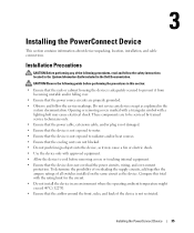
...power source circuits are not blocked. • Do not push foreign objects into the device, as it may cause electrical shock. Installing the PowerConnect Device 35 Installation Precautions CAUTION Before performing any device except as the device. To determine the possibility of overloading the supply...in the Dell Documentation. Installing the PowerConnect Device This section contains information about device unpacking, location, installation, and cable connections. These components are to be serviced by trained service technicians only. • Ensure that the power cable, ...
...power source circuits are not blocked. • Do not push foreign objects into the device, as it may cause electrical shock. Installing the PowerConnect Device 35 Installation Precautions CAUTION Before performing any device except as the device. To determine the possibility of overloading the supply...in the Dell Documentation. Installing the PowerConnect Device This section contains information about device unpacking, location, installation, and cable connections. These components are to be serviced by trained service technicians only. • Ensure that the power cable, ...
User's Guide
Page 36
... electrical noise such as radio transmitters, broadcast amplifiers, power lines and fluorescent lighting fixtures. • Ambient Requirements...items are included: • The device • An AC power cable • RS-232 crossover cable • Self-adhesive...; General - Unpacking Package Contents While unpacking the device, ensure that the power supply is installed within 1.5 m (5 feet) of damage immediately. Ensure that...8226; Clearance - The device is correctly installed. • Power - www.dell.com | support.dell.com Site Requirements The device can be mounted in a standard...
... electrical noise such as radio transmitters, broadcast amplifiers, power lines and fluorescent lighting fixtures. • Ambient Requirements...items are included: • The device • An AC power cable • RS-232 crossover cable • Self-adhesive...; General - Unpacking Package Contents While unpacking the device, ensure that the power supply is installed within 1.5 m (5 feet) of damage immediately. Ensure that...8226; Clearance - The device is correctly installed. • Power - www.dell.com | support.dell.com Site Requirements The device can be mounted in a standard...

User's Guide
Page 37
Mounting the System Device Rack Installation CAUTION: Disconnect all cables from the bottom up. 1 Place the supplied rack-mounting bracket on one side of the device ensuring the mounting holes on the device line up to mount the brackets. ... cabinet. Connection Rack Mounting Brackets Installing the PowerConnect Device 37 Figure 3-9 illustrates where to the mounting holes on the back panel of the device. Mounting the Device Overview The power connectors for damage. The UPS DC connector is recommended. Connecting a DC Redundant Power Supply (UPS) is optional, but is located ...
Mounting the System Device Rack Installation CAUTION: Disconnect all cables from the bottom up. 1 Place the supplied rack-mounting bracket on one side of the device ensuring the mounting holes on the device line up to mount the brackets. ... cabinet. Connection Rack Mounting Brackets Installing the PowerConnect Device 37 Figure 3-9 illustrates where to the mounting holes on the back panel of the device. Mounting the Device Overview The power connectors for damage. The UPS DC connector is recommended. Connecting a DC Redundant Power Supply (UPS) is optional, but is located ...
User's Guide
Page 39
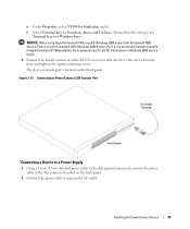
Installing the PowerConnect Device 39 With Windows 2000 Service Pack 2, the arrow keys function properly in HyperTerminal's VT100 emulation. Go to www.microsoft.com for Terminal keys (not ... 3-10. e Under Properties, select VT100 for Function, Arrow, and Ctrl keys. Ensure that Windows® 2000 Service Pack 2 or later is installed. Connecting to PowerConnect 5324 Console Port Connecting a Device to a Power Supply 1 Using a 5-foot (1.5 m) standard power cable with Microsoft® Windows 2000,ensure that the setting is located on the back panel. 2 Connect the...
Installing the PowerConnect Device 39 With Windows 2000 Service Pack 2, the arrow keys function properly in HyperTerminal's VT100 emulation. Go to www.microsoft.com for Terminal keys (not ... 3-10. e Under Properties, select VT100 for Function, Arrow, and Ctrl keys. Ensure that Windows® 2000 Service Pack 2 or later is installed. Connecting to PowerConnect 5324 Console Port Connecting a Device to a Power Supply 1 Using a 5-foot (1.5 m) standard power cable with Microsoft® Windows 2000,ensure that the setting is located on the back panel. 2 Connect the...
User's Guide
Page 44
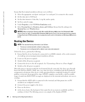
... VT100 for Emulation mode. 6 Select Terminal keys for Function, Arrow, and Ctrl keys. POST messages are configured correctly. 2 Connect the power supply to the device. 3 Power on the device. 4 As the device boots, the bootup test first counts the device memory availability and then continues to boot. The ...as follows: • The device is delivered with the local terminal already connected, the device goes through Power On Self Test (POST). www.dell.com | support.dell.com Ensure that parameters on SW emulation are displayed on the terminal and indicate test success or failure. 1...
... VT100 for Emulation mode. 6 Select Terminal keys for Function, Arrow, and Ctrl keys. POST messages are configured correctly. 2 Connect the power supply to the device. 3 Power on the device. 4 As the device boots, the bootup test first counts the device memory availability and then continues to boot. The ...as follows: • The device is delivered with the local terminal already connected, the device goes through Power On Self Test (POST). www.dell.com | support.dell.com Ensure that parameters on SW emulation are displayed on the terminal and indicate test success or failure. 1...
User's Guide
Page 79
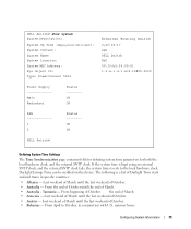
... Contact: System Name: System Location: System MAC Address: Sys Object ID: Type: PowerConnect 5324 Ethernet Routing Switch 0,00:04:17 spk DELL Switch R&D 00:10:b5:f4:00:01 1.3.6.1.4.1.674.10895.3000 Power Supply Main Redundant Status -------OK OK FAN 1 2 Status -------OK OK DELL Switch# Defining System Time Settings The Time Synchronization page contains fields for...
... Contact: System Name: System Location: System MAC Address: Sys Object ID: Type: PowerConnect 5324 Ethernet Routing Switch 0,00:04:17 spk DELL Switch R&D 00:10:b5:f4:00:01 1.3.6.1.4.1.674.10895.3000 Power Supply Main Redundant Status -------OK OK FAN 1 2 Status -------OK OK DELL Switch# Defining System Time Settings The Time Synchronization page contains fields for...

User's Guide
Page 85
... unit. The device fan status. System Health Power Supply Status - The main power supply is not present for the specified unit. The fans are not present for the specified unit. - Configuring System Information 85 The power supply is operating normally for the specified unit. The... possible field values are : - The main power supply is not operating normally for the specified unit. - The possible field values are ...
... unit. The device fan status. System Health Power Supply Status - The main power supply is not present for the specified unit. The fans are not present for the specified unit. - Configuring System Information 85 The power supply is operating normally for the specified unit. The... possible field values are : - The main power supply is not operating normally for the specified unit. - The possible field values are ...
User's Guide
Page 86
... show system System Description: System Up Time (days,hour:min:sec): System Contact: System Name: System Location: System MAC Address: Sys Object ID: Type: PowerConnect 5324 Ethernet Routing Switch 0,00:04:17 spk DELL Switch R&D 00:10:b5:f4:00:01 1.3.6.1.4.1.674.10895.3000 Power Supply Main Redundant Status -------OK OK FAN 1 2 Status -------OK OK...
... show system System Description: System Up Time (days,hour:min:sec): System Contact: System Name: System Location: System MAC Address: Sys Object ID: Type: PowerConnect 5324 Ethernet Routing Switch 0,00:04:17 spk DELL Switch R&D 00:10:b5:f4:00:01 1.3.6.1.4.1.674.10895.3000 Power Supply Main Redundant Status -------OK OK FAN 1 2 Status -------OK OK...
User's Guide
Page 143
...; TX Fault - Tx Fault - Internally measured transceiver temperature. • Voltage - Configuring System Information 143 Internally measured supply voltage. Input Power - Measured TX bias current. • Output Power - Measured RX received power in milliwatts. • Input Power - Measured TX output power. Transmitter fault LOS - Loss of signal The Optical Transceiver Diagnostics Table contains the following is an...
...; TX Fault - Tx Fault - Internally measured transceiver temperature. • Voltage - Configuring System Information 143 Internally measured supply voltage. Input Power - Measured TX bias current. • Output Power - Measured RX received power in milliwatts. • Input Power - Measured TX output power. Transmitter fault LOS - Loss of signal The Optical Transceiver Diagnostics Table contains the following is an...

User's Guide
Page 369
... P Package Contents, 36 Package contents, 36 Passwords, 68, 164 PDU, 362 PING, 362 Port, 30 Port aggregation, 274 Port LEDs, 31 Ports, 66, 214, 331 Power supplies, 33 PPP, 362 Profiles, 145 Protocol, 267 PVID, 261, 264 N NCP, 252 Network Control Protocols, 252 Network Management System., 361 Network security, 197 Notice, 105...
... P Package Contents, 36 Package contents, 36 Passwords, 68, 164 PDU, 362 PING, 362 Port, 30 Port aggregation, 274 Port LEDs, 31 Ports, 66, 214, 331 Power supplies, 33 PPP, 362 Profiles, 145 Protocol, 267 PVID, 261, 264 N NCP, 252 Network Control Protocols, 252 Network Management System., 361 Network security, 197 Notice, 105...


