Command Line Interface Guide
Page 125
... supported and are automatically detected. • Mdix ON: It is possible to connect to a PC only with a cross cable. • If MDIX is set to "no back-pressure Default Configuration Back Pressure is enabled on a given interface. Ethernet Configuration Commands... disable Back Pressure, use either an ethernet standard cross-over cable to connect to a PC, or an ethernet standard cable to connect to another switch ONLY with a normal cable and to connect to another switch. Console(config)# interface ethernet g5 Console(config-if)# mdix auto back-pressure The back-pressure Interface...
... supported and are automatically detected. • Mdix ON: It is possible to connect to a PC only with a cross cable. • If MDIX is set to "no back-pressure Default Configuration Back Pressure is enabled on a given interface. Ethernet Configuration Commands... disable Back Pressure, use either an ethernet standard cross-over cable to connect to a PC, or an ethernet standard cable to connect to another switch ONLY with a normal cable and to connect to another switch. Console(config)# interface ethernet g5 Console(config-if)# mdix auto back-pressure The back-pressure Interface...
Command Line Interface Guide
Page 195
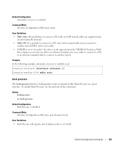
...EXEC mode command display the last TDR (Time Domain Reflectometry) tests on the cable attached to a port. NOTE: The maximum distance VCT can function is down. Console# test copper-port tdr g3 Cable is open at 100 meters show copper-ports tdr The show copper-ports tdr ...test copper-port tdr Privileged EXEC mode command diagnoses with TDR (Time Domain Reflectometry) technology the quality and characteristics of a copper cable attached to port g3. Default Configuration This command has no default configuration. Default Configuration This command has no default configuration. PHY ...
...EXEC mode command display the last TDR (Time Domain Reflectometry) tests on the cable attached to a port. NOTE: The maximum distance VCT can function is down. Console# test copper-port tdr g3 Cable is open at 100 meters show copper-ports tdr The show copper-ports tdr ...test copper-port tdr Privileged EXEC mode command diagnoses with TDR (Time Domain Reflectometry) technology the quality and characteristics of a copper cable attached to port g3. Default Configuration This command has no default configuration. Default Configuration This command has no default configuration. PHY ...
Command Line Interface Guide
Page 196
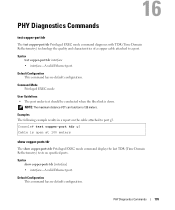
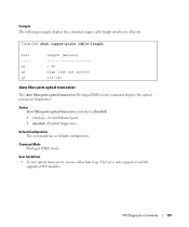
...Privileged EXEC mode command displays the estimated copper cable length attached to a port. Command Mode Privileged EXEC mode User Guidelines • The port must be active and working in 1000M. 196 PHY Diagnostics Commands www.dell.com | support.dell.com Command Mode Privileged EXEC mode User Guidelines... Domain Reflectometry) tests on all ports. show copper-ports cable-length The show copper-ports cable-length [interface] • interface-A valid Ethernet port. Date ----- 13:32:00 23 July 2003 13:32:00 23 July 2003 - Console# show copper-ports tdr Port ---g1 g2 g3 g4 ...
...Privileged EXEC mode command displays the estimated copper cable length attached to a port. Command Mode Privileged EXEC mode User Guidelines • The port must be active and working in 1000M. 196 PHY Diagnostics Commands www.dell.com | support.dell.com Command Mode Privileged EXEC mode User Guidelines... Domain Reflectometry) tests on all ports. show copper-ports cable-length The show copper-ports cable-length [interface] • interface-A valid Ethernet port. Date ----- 13:32:00 23 July 2003 13:32:00 23 July 2003 - Console# show copper-ports tdr Port ---g1 g2 g3 g4 ...
Command Line Interface Guide
Page 197
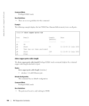
... optical transceiver diagnostics. Command Mode Privileged EXEC mode User Guidelines • To test optical transceivers, ensure a fiber link is only supported on Dell supported SFP modules. Console# show copper-ports cable-length Port ---g1 g2 g3 Length [meters 50 Giga link not active 110-140 show fiber-ports optical-transceiver The show fiber...
... optical transceiver diagnostics. Command Mode Privileged EXEC mode User Guidelines • To test optical transceivers, ensure a fiber link is only supported on Dell supported SFP modules. Console# show copper-ports cable-length Port ---g1 g2 g3 Length [meters 50 Giga link not active 110-140 show fiber-ports optical-transceiver The show fiber...
User's Guide
Page 30
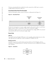
www.dell.com | support.dell.com The device automatically detects whether the cable connected to an RJ-45 port is crossed or straight through, and functions either 110V or 220V power supplies. Figure 2-4. The default baud rate is ... is used for debugging, software download, etc. The baud rate can be activated automatically in the Figure 2-4. RS-232 Console Port One DB-9 connector for power, as 1000Base-SX or LX. PowerConnect Back Panel Port Description The device back panel contains connectors for a serial terminal connection which is to connect a Redundant Power...
www.dell.com | support.dell.com The device automatically detects whether the cable connected to an RJ-45 port is crossed or straight through, and functions either 110V or 220V power supplies. Figure 2-4. The default baud rate is ... is used for debugging, software download, etc. The baud rate can be activated automatically in the Figure 2-4. RS-232 Console Port One DB-9 connector for power, as 1000Base-SX or LX. PowerConnect Back Panel Port Description The device back panel contains connectors for a serial terminal connection which is to connect a Redundant Power...
User's Guide
Page 38
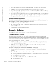
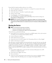
...software. 2 Ensure that the device has proper ventilation. d Set flow control to the rack with the rack screws (not provided). www.dell.com | support.dell.com 2 Insert the supplied screws into the rack mounting holes and tighten with a screwdriver. 3 Repeat the process for the rack-mounting ...up to the mounting hole on the rack. 5 Secure the unit to none. 38 Installing the PowerConnect Device To use the Console port, the following : 1 Connect an RS-232 crossover cable to the terminal running terminal emulation software for monitoring and configuring the device. b Set the data rate...
...software. 2 Ensure that the device has proper ventilation. d Set flow control to the rack with the rack screws (not provided). www.dell.com | support.dell.com 2 Insert the supplied screws into the rack mounting holes and tighten with a screwdriver. 3 Repeat the process for the rack-mounting ...up to the mounting hole on the rack. 5 Secure the unit to none. 38 Installing the PowerConnect Device To use the Console port, the following : 1 Connect an RS-232 crossover cable to the terminal running terminal emulation software for monitoring and configuring the device. b Set the data rate...
User's Guide
Page 39
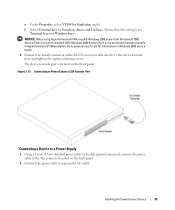
Figure 3-10. The device Console port is installed. Installing the PowerConnect Device 39 Connecting to PowerConnect 5324 Console Port Connecting a Device to a Power Supply 1 Using a 5-foot (1.5 m) standard power cable with Microsoft® Windows 2000,ensure that the setting is for information on the front...keys). NOTICE: When using HyperTerminal with safety ground connected, connect the power cable to the AC connector located on the back panel. 2 Connect the power cable to the device Console port, and tighten the captive retaining screws. Ensure that Windows® 2000 ...
Figure 3-10. The device Console port is installed. Installing the PowerConnect Device 39 Connecting to PowerConnect 5324 Console Port Connecting a Device to a Power Supply 1 Using a 5-foot (1.5 m) standard power cable with Microsoft® Windows 2000,ensure that the setting is for information on the front...keys). NOTICE: When using HyperTerminal with safety ground connected, connect the power cable to the AC connector located on the back panel. 2 Connect the power cable to the device Console port, and tighten the captive retaining screws. Ensure that Windows® 2000 ...
User's Guide
Page 44
...are displayed on the terminal and indicate test success or failure. 1 Ensure that the ASCII cable is connected to the terminal, and that parameters on SW emulation are configured correctly. 2 ...as follows: 1 Select the appropriate serial port (serial port 1 or serial port 2) to connect to the console. 2 Set the data rate to 9600 baud. 3 Set the data format to 8 data bits, 1 ...parity. 4 Set flow control to www.microsoft.com for Terminal keys (not Windows keys). www.dell.com | support.dell.com Ensure that the terminal emulation software is set as follows: • The device is delivered...
...are displayed on the terminal and indicate test success or failure. 1 Ensure that the ASCII cable is connected to the terminal, and that parameters on SW emulation are configured correctly. 2 ...as follows: 1 Select the appropriate serial port (serial port 1 or serial port 2) to connect to the console. 2 Set the data rate to 9600 baud. 3 Set the data format to 8 data bits, 1 ...parity. 4 Set flow control to www.microsoft.com for Terminal keys (not Windows keys). www.dell.com | support.dell.com Ensure that the terminal emulation software is set as follows: • The device is delivered...
User's Guide
Page 141
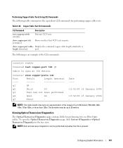
... 13:32:00 15 January 2004 - show copper-port tdr [interface] Shows results of the CLI commands: console> enable Console# test copper-port tdr g3 Cable is an example of last VCT tests on Fiber Optic cables. The following table summarizes the equivalent CLI commands for performing tests on ports. NOTE: Optical transceiver diagnostics...
... 13:32:00 15 January 2004 - show copper-port tdr [interface] Shows results of the CLI commands: console> enable Console# test copper-port tdr g3 Cable is an example of last VCT tests on Fiber Optic cables. The following table summarizes the equivalent CLI commands for performing tests on ports. NOTE: Optical transceiver diagnostics...
User's Guide
Page 143
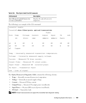
Fiber Optic Cable Test CLI Commands CLI Command show fiber-ports optical-transceiver Power Port Temp Voltage Current Output Input TX LOS (C) (Volt) (mA) (mWatt) (mWatt...Transmitter fault. Configuring System Information 143 Table 6-34. Internally measured supply voltage. Transmitter fault LOS - Voltage - Output Power - Loss of the CLI command: console> enable Console# show fiber-ports optical-transceiver [interface][detailed] Description Displays the optical transceiver diagnostics. Measured TX output power in milliwatts. • TX Fault - Internally ...
Fiber Optic Cable Test CLI Commands CLI Command show fiber-ports optical-transceiver Power Port Temp Voltage Current Output Input TX LOS (C) (Volt) (mA) (mWatt) (mWatt...Transmitter fault. Configuring System Information 143 Table 6-34. Internally measured supply voltage. Transmitter fault LOS - Voltage - Output Power - Loss of the CLI command: console> enable Console# show fiber-ports optical-transceiver [interface][detailed] Description Displays the optical transceiver diagnostics. Measured TX output power in milliwatts. • TX Fault - Internally ...

User's Guide
Page 351
Table 10-99. Port Specifications Device Specification PowerConnect 5324 • 24 GE ports • 4 SFP ports • RS-232 Console port Port Types RJ-45 • 10 Base-T • 100 Base-T • 1000 Base-T SFP Supports Standard Small Form-Factor Gigabit Plug Transceivers Port Settings &#... port types, as well as, a description of Line Blocking • Auto MDI/MDIX • Port Mirroring • Broadcast Storm Control Device Specifications 351 Port and Cable Specifications This section describes the port specifications.
Table 10-99. Port Specifications Device Specification PowerConnect 5324 • 24 GE ports • 4 SFP ports • RS-232 Console port Port Types RJ-45 • 10 Base-T • 100 Base-T • 1000 Base-T SFP Supports Standard Small Form-Factor Gigabit Plug Transceivers Port Settings &#... port types, as well as, a description of Line Blocking • Auto MDI/MDIX • Port Mirroring • Broadcast Storm Control Device Specifications 351 Port and Cable Specifications This section describes the port specifications.
User's Guide
Page 367
... 41 B Back panels, 33 Backup file, 186 BGP, 356 BootP, 356 BPDU, 356 Bridge Protocol Data Unit, 356 Broadcast, 120 Buttons, 67 C Cables, 139, 141 CIDR, 357 Class of Service, 22 CLI, 25 CLI Examples, 73 Command Line Interface, 25 Command Mode Overview, 70 Communities, 180 Community ...table, 177 Configuration, 48 Configuration file, 187 Configuring ARP, 132 Console, 106, 155 CoS, 22, 342 Critical, 105 D DC unit, 33-34 Debug, 105 Default Gateway, 119 Default settings, 192 Defining device information, ...
... 41 B Back panels, 33 Backup file, 186 BGP, 356 BootP, 356 BPDU, 356 Bridge Protocol Data Unit, 356 Broadcast, 120 Buttons, 67 C Cables, 139, 141 CIDR, 357 Class of Service, 22 CLI, 25 CLI Examples, 73 Command Line Interface, 25 Command Mode Overview, 70 Communities, 180 Community ...table, 177 Configuration, 48 Configuration file, 187 Configuring ARP, 132 Console, 106, 155 CoS, 22, 342 Critical, 105 D DC unit, 33-34 Debug, 105 Default Gateway, 119 Default settings, 192 Defining device information, ...


