
User's Guide
Page 3
... Description 9 PowerConnect 2808 9 PowerConnect 2816 9 PowerConnect 2824 10 PowerConnect 2848 10 Summary of PowerConnect Models 11 Features 11 General Features 11 MAC Address Supported Features 13 Layer 2 Features 13 VLAN Supported Features 14 Spanning Tree Protocol Features 15 Class of Service (CoS) Features 16 Ethernet Switch Management Features 16 2 Hardware Description 17 Switch Port Configurations 17 PowerConnect 28xx Front...
... Description 9 PowerConnect 2808 9 PowerConnect 2816 9 PowerConnect 2824 10 PowerConnect 2848 10 Summary of PowerConnect Models 11 Features 11 General Features 11 MAC Address Supported Features 13 Layer 2 Features 13 VLAN Supported Features 14 Spanning Tree Protocol Features 15 Class of Service (CoS) Features 16 Ethernet Switch Management Features 16 2 Hardware Description 17 Switch Port Configurations 17 PowerConnect 28xx Front...
User's Guide
Page 4
Power Connectors 26 Internal Power Supply Connector 26 3 Installing the PowerConnect Device 27 Installation Precautions 27 Site Requirements 28 Unpacking 28 Package Contents 28 Unpacking the Device 28 Mounting the Device 29 Overview 29 Device Rack ... RJ-45 Connections for 10/100/1000BaseT Ports 35 Port Default Settings 36 Auto-Negotiation 36 MDI/MDIX 36 Flow Control 36 Back Pressure 36 Switching Port Default Settings 37 4 Starting and Configuring the Device 39 Booting the Device - Managed Mode 41 Advanced Configuration 44 Retrieving an IP Address From a DHCP...
Power Connectors 26 Internal Power Supply Connector 26 3 Installing the PowerConnect Device 27 Installation Precautions 27 Site Requirements 28 Unpacking 28 Package Contents 28 Unpacking the Device 28 Mounting the Device 29 Overview 29 Device Rack ... RJ-45 Connections for 10/100/1000BaseT Ports 35 Port Default Settings 36 Auto-Negotiation 36 MDI/MDIX 36 Flow Control 36 Back Pressure 36 Switching Port Default Settings 37 4 Starting and Configuring the Device 39 Booting the Device - Managed Mode 41 Advanced Configuration 44 Retrieving an IP Address From a DHCP...
User's Guide
Page 5
... TFTP Server 47 Management Modes 49 Default Values 49 Transitioning Between Modes 50 Returning to Managed Mode 51 5 Using Dell OpenManage Switch Administrator 53 Understanding the Interface 53 Device Representation 54 Using the Switch Administrator Buttons 55 Information Buttons 55 Device Management Buttons 56 Starting the Application 56 Access Levels 56 6 Configuring System...
... TFTP Server 47 Management Modes 49 Default Values 49 Transitioning Between Modes 50 Returning to Managed Mode 51 5 Using Dell OpenManage Switch Administrator 53 Understanding the Interface 53 Device Representation 54 Using the Switch Administrator Buttons 55 Information Buttons 55 Device Management Buttons 56 Starting the Application 56 Access Levels 56 6 Configuring System...
User's Guide
Page 6
... Excluding Addresses 87 Manually Allocating IP Addresses (Static Hosts 89 Configuring Address Binding 92 Defining Advanced Settings 93 Configuring General Device Parameters 93 7 Configuring Device Switching 95 Configuring Network Security 95 Configuring Port Based Authentication 96 Configuring Advanced Port Based Authentication 100 Authenticating Users 102 Configuring Ports 103 Defining Port Parameters...
... Excluding Addresses 87 Manually Allocating IP Addresses (Static Hosts 89 Configuring Address Binding 92 Defining Advanced Settings 93 Configuring General Device Parameters 93 7 Configuring Device Switching 95 Configuring Network Security 95 Configuring Port Based Authentication 96 Configuring Advanced Port Based Authentication 100 Authenticating Users 102 Configuring Ports 103 Defining Port Parameters...

User's Guide
Page 9
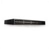
... to medium business that require high performance edge connectivity. PowerConnect 2808 The following figure illustrates the PowerConnect 2816 front panel. Dell PowerConnect 28xx Systems User Guide 9 The PowerConnect management features are ideal for installing, configuring and maintaining the PowerConnect 2808, PowerConnect 2816, PowerConnect 2824, and PowerConnect 2848 Webmanaged Gigabit Ethernet switches. These PowerConnect devices are designed to minimize administrative management effort, while...
... to medium business that require high performance edge connectivity. PowerConnect 2808 The following figure illustrates the PowerConnect 2816 front panel. Dell PowerConnect 28xx Systems User Guide 9 The PowerConnect management features are ideal for installing, configuring and maintaining the PowerConnect 2808, PowerConnect 2816, PowerConnect 2824, and PowerConnect 2848 Webmanaged Gigabit Ethernet switches. These PowerConnect devices are designed to minimize administrative management effort, while...

User's Guide
Page 11
...where the HOL blocking prevention mechanism is disabled on the whole system. Provides switch management through the web interface. • Unmanaged Mode - By default,... Modes The device supports the following table summarizes the PowerConnect models. Table 1-1. PowerConnect Models Model PowerConnect 2808 PowerConnect 2816 PowerConnect 2824 PowerConnect 2848 Copper Ports/ RJ-45 Connectors Optical Ports/ GbE ...delays and frame loss caused by traffic competing for additional incoming traffic. Dell PowerConnect 28xx Systems User Guide 11 Fans baud rate is active at the...
...where the HOL blocking prevention mechanism is disabled on the whole system. Provides switch management through the web interface. • Unmanaged Mode - By default,... Modes The device supports the following table summarizes the PowerConnect models. Table 1-1. PowerConnect Models Model PowerConnect 2808 PowerConnect 2816 PowerConnect 2824 PowerConnect 2848 Copper Ports/ RJ-45 Connectors Optical Ports/ GbE ...delays and frame loss caused by traffic competing for additional incoming traffic. Dell PowerConnect 28xx Systems User Guide 11 Fans baud rate is active at the...
User's Guide
Page 12
...their transmission capabilities. AutoMDI/MDIX Support The switch automatically detects whether the cable connected to advertise modes of this facility are detected: • Cable Type and Status • Cable Length • Fault-Distance 12 Dell PowerConnect 28xx Systems User Guide This feature is ...automatically enabled for hubs and switches is known as cable opens and cable shorts on copper links. Auto Negotiation Auto negotiation allows...
...their transmission capabilities. AutoMDI/MDIX Support The switch automatically detects whether the cable connected to advertise modes of this facility are detected: • Cable Type and Status • Cable Length • Fault-Distance 12 Dell PowerConnect 28xx Systems User Guide This feature is ...automatically enabled for hubs and switches is known as cable opens and cable shorts on copper links. Auto Negotiation Auto negotiation allows...

User's Guide
Page 13
... with ports by learning them from overflowing. Dell PowerConnect 28xx Systems User Guide 13 MAC Address Supported Features MAC Address Capacity Support The PowerConnect 2808, 2816, 2824 switches support a total of 8K MAC addresses, and the PowerConnect 2848 supports a total of transmit power. Auto-...Learning MAC Addresses The switch enables MAC address auto-learning from where copies of...
... with ports by learning them from overflowing. Dell PowerConnect 28xx Systems User Guide 13 MAC Address Supported Features MAC Address Capacity Support The PowerConnect 2808, 2816, 2824 switches support a total of 8K MAC addresses, and the PowerConnect 2848 supports a total of transmit power. Auto-...Learning MAC Addresses The switch enables MAC address auto-learning from where copies of...
User's Guide
Page 14
... Users can be defined with up to a monitoring port. Packets sharing common attributes can specify which Multicast routers are forwarded by the switch. Each of the ingress port and package contents. IGMP Snooping Internet Group Membership Protocol (IGMP) Snooping examines IGMP frame contents, when they... copies of Multicast, Broadcast and Unknown Unicast frames accepted and forwarded by the device from physical link disruption 14 Dell PowerConnect 28xx Systems User Guide The benefits of this facility are collections of power over Ethernet cables shorter than 40m.
... Users can be defined with up to a monitoring port. Packets sharing common attributes can specify which Multicast routers are forwarded by the switch. Each of the ingress port and package contents. IGMP Snooping Internet Group Membership Protocol (IGMP) Snooping examines IGMP frame contents, when they... copies of Multicast, Broadcast and Unknown Unicast frames accepted and forwarded by the device from physical link disruption 14 Dell PowerConnect 28xx Systems User Guide The benefits of this facility are collections of power over Ethernet cables shorter than 40m.

User's Guide
Page 15
... Link option bypasses this time, STP detects possible loops, allowing time for status changes to propagate and for the switch Dell PowerConnect 28xx Systems User Guide 15 BootP and DHCP Clients DHCP (Dynamic Host Configuration Protocol) enables additional setup parameters to be used... client then continuously attempts to find a BootP server, by sending BootP requests to enable faster convergence, without creating forwarding loops. The switch can take up to 30-60 seconds to converge. • Higher bandwidth connections • Improved bandwidth granularity • High bandwidth ...
... Link option bypasses this time, STP detects possible loops, allowing time for status changes to propagate and for the switch Dell PowerConnect 28xx Systems User Guide 15 BootP and DHCP Clients DHCP (Dynamic Host Configuration Protocol) enables additional setup parameters to be used... client then continuously attempts to find a BootP server, by sending BootP requests to enable faster convergence, without creating forwarding loops. The switch can take up to 30-60 seconds to converge. • Higher bandwidth connections • Improved bandwidth granularity • High bandwidth ...

User's Guide
Page 16
...is classified and sent to the destination. Class of Service (CoS) Features The PowerConnect 28xx system enables users to define various services for traffic classes of the queues. The switches support four queues per port. A CoS is an extension to one RMON group ...underlying mechanism for Ethernet statistics. The PowerConnect 28xx system can classify according to view the results, using the Web management interface in the system. 16 Dell PowerConnect 28xx Systems User Guide TFTP Trivial File Transfer Protocol The PowerConnect 28xx switches support software boot image and software ...
...is classified and sent to the destination. Class of Service (CoS) Features The PowerConnect 28xx system enables users to define various services for traffic classes of the queues. The switches support four queues per port. A CoS is an extension to one RMON group ...underlying mechanism for Ethernet statistics. The PowerConnect 28xx system can classify according to view the results, using the Web management interface in the system. 16 Dell PowerConnect 28xx Systems User Guide TFTP Trivial File Transfer Protocol The PowerConnect 28xx switches support software boot image and software ...

User's Guide
Page 17
... status and the management mode. On the left side of the PowerConnect 28xx switches. For more information about management modes and transitioning between management modes and to transition between them, see "Management Modes" on page 49. Dell PowerConnect 28xx Systems User Guide 17 Figure 2-1. A Mode push-button, located on the right side on the...
... status and the management mode. On the left side of the PowerConnect 28xx switches. For more information about management modes and transitioning between management modes and to transition between them, see "Management Modes" on page 49. Dell PowerConnect 28xx Systems User Guide 17 Figure 2-1. A Mode push-button, located on the right side on the...

User's Guide
Page 18
... left to indicate the port status. The Power LED on the front panel indicates whether the device is powered on page 49. PowerConnect 2816 Front Panel On the front panel there are 16 ports which are LEDs to right. For more information about management modes and... LED which indicates the Ethernet switch operational status and the management mode. On each port there are numbered 1 to 16, top down and left side of the front panel is used to reset the device. PowerConnect 2816 Back Panel 18 Dell PowerConnect 28xx Systems User Guide PowerConnect 2808 Back Panel Figure 2-3. Figure...
... left to indicate the port status. The Power LED on the front panel indicates whether the device is powered on page 49. PowerConnect 2816 Front Panel On the front panel there are 16 ports which are LEDs to right. For more information about management modes and... LED which indicates the Ethernet switch operational status and the management mode. On each port there are numbered 1 to 16, top down and left side of the front panel is used to reset the device. PowerConnect 2816 Back Panel 18 Dell PowerConnect 28xx Systems User Guide PowerConnect 2808 Back Panel Figure 2-3. Figure...

User's Guide
Page 19
...ports are two SFP (Small Form-Factor Plugable) ports, designated as ports 23 and 24, for swappable optical transceiver, which indicates the Ethernet switch operational status and the management mode. A Mode push-button, located on the right side on or not. NOTE: The system can be ...port can switch from the RJ-45 to right. PowerConnect 2824 Front Panel On the front panel there are 24 ports which are logical ports with two physical connections: • An RJ-45 connection for Twisted Pair (TP) copper cabling • An SFP port for fiber connection. Dell PowerConnect 28xx ...
...ports are two SFP (Small Form-Factor Plugable) ports, designated as ports 23 and 24, for swappable optical transceiver, which indicates the Ethernet switch operational status and the management mode. A Mode push-button, located on the right side on or not. NOTE: The system can be ...port can switch from the RJ-45 to right. PowerConnect 2824 Front Panel On the front panel there are 24 ports which are logical ports with two physical connections: • An RJ-45 connection for Twisted Pair (TP) copper cabling • An SFP port for fiber connection. Dell PowerConnect 28xx ...

User's Guide
Page 20
... • An SFP port for fiber connection. Port features and port controls are numbered 1 to 48, top down and left to right. PowerConnect 2848 Front Panel On the front panel there are LEDs to the SFP (or vice versa) without resetting the device. NOTE: Only one time. The... Managed Mode LED which indicates the Ethernet switch operational status and the management mode. A Mode push- 20 Dell PowerConnect 28xx Systems User Guide On the top right side of a combo port can switch from the RJ-45 to indicate the port status. PowerConnect 2824 Back Panel Figure 2-7. The system ...
... • An SFP port for fiber connection. Port features and port controls are numbered 1 to 48, top down and left to right. PowerConnect 2848 Front Panel On the front panel there are LEDs to the SFP (or vice versa) without resetting the device. NOTE: Only one time. The... Managed Mode LED which indicates the Ethernet switch operational status and the management mode. A Mode push- 20 Dell PowerConnect 28xx Systems User Guide On the top right side of a combo port can switch from the RJ-45 to indicate the port status. PowerConnect 2824 Back Panel Figure 2-7. The system ...

User's Guide
Page 21
....32 in) • Depth - 255 mm (10.04 in.) LED Definitions The front panel contains LEDs that indicate the status of the PowerConnect 2848 device. PowerConnect 2848 Back Panel Physical Dimensions The PowerConnect 2808 switch has the following physical dimensions: • Height - 43.2 mm (1.7008 in.) • Width - 256 mm (10.079 in.) • Depth - 161... back panel contains an AC Power Supply Interface. Figure 2-8. button, located on the right side on the front panel is used to reset the device. Dell PowerConnect 28xx Systems User Guide 21 Fans are provided on page 49.
....32 in) • Depth - 255 mm (10.04 in.) LED Definitions The front panel contains LEDs that indicate the status of the PowerConnect 2848 device. PowerConnect 2848 Back Panel Physical Dimensions The PowerConnect 2808 switch has the following physical dimensions: • Height - 43.2 mm (1.7008 in.) • Width - 256 mm (10.079 in.) • Depth - 161... back panel contains an AC Power Supply Interface. Figure 2-8. button, located on the right side on the front panel is used to reset the device. Dell PowerConnect 28xx Systems User Guide 21 Fans are provided on page 49.

User's Guide
Page 22
...LED indications. Table 2-2. Indicates the switch is indicated on . The following figure illustrates the RJ-45 10/100/1000BASE-T LEDs. 22 Dell PowerConnect 28xx Systems User Guide Table 2-3. No valid image. Fan LED (2824/2848 only) On the PowerConnect 2824 and PowerConnect 2848 front panel there is a Power... diagnostics in Managed Mode. Power LED On the PowerConnect 28xx front panel there is a fan LED. Power LED Indications LED Color Green Solid Off Description The switch is a Managed Mode LED monitoring the switch node as well as indicating diagnostic test results. ...
...LED indications. Table 2-2. Indicates the switch is indicated on . The following figure illustrates the RJ-45 10/100/1000BASE-T LEDs. 22 Dell PowerConnect 28xx Systems User Guide Table 2-3. No valid image. Fan LED (2824/2848 only) On the PowerConnect 2824 and PowerConnect 2848 front panel there is a Power... diagnostics in Managed Mode. Power LED On the PowerConnect 28xx front panel there is a fan LED. Power LED Indications LED Color Green Solid Off Description The switch is a Managed Mode LED monitoring the switch node as well as indicating diagnostic test results. ...

User's Guide
Page 23
... between Managed Mode and Unmanaged (or Secure) Mode and for changing between them, see "Management Modes" on the front panel. Dell PowerConnect 28xx Systems User Guide 23 No link is occurring. The port is linked at 1000 Mbps. RJ-45 Copper based 10/100/...Green Solid Link is transmitting or receiving data at least 7 seconds. Switch Ventilation Fan The PowerConnect 2848 switch has three fans and the PowerConnect 2824 switch has one fan for at 10 or 100 Mbps. The PowerConnect 2808 and PowerConnect 2816 devices have no internal fans. Figure 2-9. RJ-45 Copper-...
... between Managed Mode and Unmanaged (or Secure) Mode and for changing between them, see "Management Modes" on the front panel. Dell PowerConnect 28xx Systems User Guide 23 No link is occurring. The port is linked at 1000 Mbps. RJ-45 Copper based 10/100/...Green Solid Link is transmitting or receiving data at least 7 seconds. Switch Ventilation Fan The PowerConnect 2848 switch has three fans and the PowerConnect 2824 switch has one fan for at 10 or 100 Mbps. The PowerConnect 2808 and PowerConnect 2816 devices have no internal fans. Figure 2-9. RJ-45 Copper-...
User's Guide
Page 24
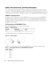
...copper Twisted-Pair ports. For each device, the supported mode is set to the switch physical interface ports, located on the front panel. Table 2-7. RJ-45 Connections for ...includes test parameters that are supported. Figure 2-10. Cables, Port Connections, and Pinout Information This section explains the switch physical interfaces, and provides information about cables and port connections. RJ-45 Pin Numbers The RJ-45 pin number allocation.../100/ 1000BASE-T Ethernet Port Pin No 1 2 3 4 5 Function TxRx 1+ TxRx 1TxRx 2+ TxRx 2TxRx 3+ 24 Dell PowerConnect 28xx Systems User Guide
...copper Twisted-Pair ports. For each device, the supported mode is set to the switch physical interface ports, located on the front panel. Table 2-7. RJ-45 Connections for ...includes test parameters that are supported. Figure 2-10. Cables, Port Connections, and Pinout Information This section explains the switch physical interfaces, and provides information about cables and port connections. RJ-45 Pin Numbers The RJ-45 pin number allocation.../100/ 1000BASE-T Ethernet Port Pin No 1 2 3 4 5 Function TxRx 1+ TxRx 1TxRx 2+ TxRx 2TxRx 3+ 24 Dell PowerConnect 28xx Systems User Guide

User's Guide
Page 25
... Receiver ground (common with transmitter ground) Receiver ground (common with transmitter ground) Receiver ground (common with transmitter ground) Dell PowerConnect 28xx Systems User Guide 25 The system can be disabled and ignored. NOTE: If both RJ-45 and SFP ports are... 1; no connection required. PowerConnect 2824 switch supports SFP diagnostics. Loss of parameters that can switch from the RJ-45 to the system administrator. SFP Ports The PowerConnect 2824 switch supports two SFP transceivers combo ports, and the PowerConnect 2848 switch supports four SFP transceivers combo...
... Receiver ground (common with transmitter ground) Receiver ground (common with transmitter ground) Receiver ground (common with transmitter ground) Dell PowerConnect 28xx Systems User Guide 25 The system can be disabled and ignored. NOTE: If both RJ-45 and SFP ports are... 1; no connection required. PowerConnect 2824 switch supports SFP diagnostics. Loss of parameters that can switch from the RJ-45 to the system administrator. SFP Ports The PowerConnect 2824 switch supports two SFP transceivers combo ports, and the PowerConnect 2848 switch supports four SFP transceivers combo...


