User's Guide
Page 5
...Through TFTP Server 47 Management Modes 49 Default Values 49 Transitioning Between Modes 50 Returning to Managed Mode 51 5 Using Dell OpenManage Switch Administrator 53 Understanding the Interface 53 Device Representation 54 Using the Switch Administrator Buttons 55 Information Buttons 55 ...Levels 56 6 Configuring System Information 59 Defining General Device Information 59 Viewing Device Information 59 Viewing the Versions Page 61 Resetting the Device 62 Entering Secure Mode 63 Defining Device IP Addresses 64 Defining IP Interface Parameters 64 Running Cable Diagnostics 65...
...Through TFTP Server 47 Management Modes 49 Default Values 49 Transitioning Between Modes 50 Returning to Managed Mode 51 5 Using Dell OpenManage Switch Administrator 53 Understanding the Interface 53 Device Representation 54 Using the Switch Administrator Buttons 55 Information Buttons 55 ...Levels 56 6 Configuring System Information 59 Defining General Device Information 59 Viewing Device Information 59 Viewing the Versions Page 61 Resetting the Device 62 Entering Secure Mode 63 Defining Device IP Addresses 64 Defining IP Interface Parameters 64 Running Cable Diagnostics 65...

User's Guide
Page 17
...Emitting Diode) to indicate the port status. On each port there are numbered 1 to 8, top down and left to reset the device. For more information about management modes and transitioning between management modes and to right. These ports support autonegotiation, ...panel indicates whether the device is used to a network. Figure 2-1. Dell PowerConnect 28xx Systems User Guide 17 Hardware Description Switch Port Configurations PowerConnect 28xx Front and Back Panel Port Description The Dell™ PowerConnect™ 28xx switches use 10/100/1000BASE-T ports on or not.
...Emitting Diode) to indicate the port status. On each port there are numbered 1 to 8, top down and left to reset the device. For more information about management modes and transitioning between management modes and to right. These ports support autonegotiation, ...panel indicates whether the device is used to a network. Figure 2-1. Dell PowerConnect 28xx Systems User Guide 17 Hardware Description Switch Port Configurations PowerConnect 28xx Front and Back Panel Port Description The Dell™ PowerConnect™ 28xx switches use 10/100/1000BASE-T ports on or not.

User's Guide
Page 18
... Back Panel 18 Dell PowerConnect 28xx Systems User Guide Figure 2-2. For more information about management modes and transitioning between management modes and to reset the device. On the left side of the front panel is the Managed Mode LED which are numbered 1 to 16, top down and left to ...indicate the port status. On each port there are 16 ports which indicates the Ethernet switch operational status and the management mode. PowerConnect 2808...
... Back Panel 18 Dell PowerConnect 28xx Systems User Guide Figure 2-2. For more information about management modes and transitioning between management modes and to reset the device. On the left side of the front panel is the Managed Mode LED which are numbered 1 to 16, top down and left to ...indicate the port status. On each port there are 16 ports which indicates the Ethernet switch operational status and the management mode. PowerConnect 2808...

User's Guide
Page 19
... Power LED on the front panel indicates whether the device is powered on a combo port, and utilizes the information in all the control interfaces. Dell PowerConnect 28xx Systems User Guide 19 On the front panel is used on or not. A Mode push-button, located on the right side on the... status and the management mode. For more information about management modes and transitioning between management modes and to the SFP (or vice versa) without resetting the device. If both RJ-45 and SFP ports are logical ports with two physical connections: • An RJ-45 connection for Twisted Pair...
... Power LED on the front panel indicates whether the device is powered on a combo port, and utilizes the information in all the control interfaces. Dell PowerConnect 28xx Systems User Guide 19 On the front panel is used on or not. A Mode push-button, located on the right side on the... status and the management mode. For more information about management modes and transitioning between management modes and to the SFP (or vice versa) without resetting the device. If both RJ-45 and SFP ports are logical ports with two physical connections: • An RJ-45 connection for Twisted Pair...

User's Guide
Page 20
... fan operations status, and the Power LED on the front panel indicates whether the device is the Managed Mode LED which are LEDs to right. PowerConnect 2848 Front Panel On the front panel there are four SFP (Small Form-Factor Plugable) ports, designated as ports 45, 46, 47 and 48, ... the top right side of a combo port can switch from the RJ-45 to the SFP (or vice versa) without resetting the device. A Mode push- 20 Dell PowerConnect 28xx Systems User Guide PowerConnect 2824 Back Panel Figure 2-7. On each port, there are numbered 1 to 48, top down and left to indicate the port...
... fan operations status, and the Power LED on the front panel indicates whether the device is the Managed Mode LED which are LEDs to right. PowerConnect 2848 Front Panel On the front panel there are four SFP (Small Form-Factor Plugable) ports, designated as ports 45, 46, 47 and 48, ... the top right side of a combo port can switch from the RJ-45 to the SFP (or vice versa) without resetting the device. A Mode push- 20 Dell PowerConnect 28xx Systems User Guide PowerConnect 2824 Back Panel Figure 2-7. On each port, there are numbered 1 to 48, top down and left to indicate the port...

User's Guide
Page 21
...PowerConnect 2848 Back Panel Physical Dimensions The PowerConnect 2808 switch has the following physical dimensions: • Height - 43.2 mm (1.7008 in.) • Width - 256 mm (10.079 in.) • Depth - 161.7 mm (6.366 in.) The PowerConnect 2816 and PowerConnect... front panel contains LEDs that indicate the status of the PowerConnect 2848 device. The following physical dimensions: • Height - ...Depth - 255 mm (10.04 in .) The PowerConnect 2848 switch has the following figure illustrates the back panel ...are provided on page 49. Dell PowerConnect 28xx Systems User Guide 21 ...
...PowerConnect 2848 Back Panel Physical Dimensions The PowerConnect 2808 switch has the following physical dimensions: • Height - 43.2 mm (1.7008 in.) • Width - 256 mm (10.079 in.) • Depth - 161.7 mm (6.366 in.) The PowerConnect 2816 and PowerConnect... front panel contains LEDs that indicate the status of the PowerConnect 2848 device. The following physical dimensions: • Height - ...Depth - 255 mm (10.04 in .) The PowerConnect 2848 switch has the following figure illustrates the back panel ...are provided on page 49. Dell PowerConnect 28xx Systems User Guide 21 ...

User's Guide
Page 23
...for changing between Managed Mode and Unmanaged (or Secure) Mode and for resetting the device. The Mode button is established. Off No link is occurring. Switch Ventilation Fan The PowerConnect 2848 switch has three fans and the PowerConnect 2824 switch has one fan for at 1000 Mbps. The port is... between modes, press the button normally. The port is established. No link is transmitting or receiving data at 10 or 100 Mbps. Dell PowerConnect 28xx Systems User Guide 23 Figure 2-9. RJ-45 Copper-based 10/100/1000BASE-T LEDs The RJ-45 LED indications are described in the...
...for changing between Managed Mode and Unmanaged (or Secure) Mode and for resetting the device. The Mode button is established. Off No link is occurring. Switch Ventilation Fan The PowerConnect 2848 switch has three fans and the PowerConnect 2824 switch has one fan for at 1000 Mbps. The port is... between modes, press the button normally. The port is established. No link is transmitting or receiving data at 10 or 100 Mbps. Dell PowerConnect 28xx Systems User Guide 23 Figure 2-9. RJ-45 Copper-based 10/100/1000BASE-T LEDs The RJ-45 LED indications are described in the...

User's Guide
Page 25
...reset. PowerConnect 2824 switch supports SFP diagnostics. data line for the SFP ports is listed in the control interfaces. Module definition 0; Rate select; Receiver ground (common with transmitter ground) Receiver ground (common with transmitter ground) Receiver ground (common with transmitter ground) Dell PowerConnect...operation. Table 2-7. RJ-45 Pin Number Allocation for serial ID. SFP Ports The PowerConnect 2824 switch supports two SFP transceivers combo ports, and the PowerConnect 2848 switch supports four SFP transceivers combo ports for various fiber-based modules (1000BASE-SX...
...reset. PowerConnect 2824 switch supports SFP diagnostics. data line for the SFP ports is listed in the control interfaces. Module definition 0; Rate select; Receiver ground (common with transmitter ground) Receiver ground (common with transmitter ground) Receiver ground (common with transmitter ground) Dell PowerConnect...operation. Table 2-7. RJ-45 Pin Number Allocation for serial ID. SFP Ports The PowerConnect 2824 switch supports two SFP transceivers combo ports, and the PowerConnect 2848 switch supports four SFP transceivers combo ports for various fiber-based modules (1000BASE-SX...

User's Guide
Page 45
... Procedures Startup Menu Procedures The procedures called from a DHCP server, use by technical support personnel only and are for the auto-boot message SYSTEM RESET ------ To configure the device so it will retrieve an IP address from the Startup menu cover software download, flash handling and password recovery. UART...Checksum Test PASS Boot2 Checksum Test PASS Flash Image Validation Test PASS BOOT Software Version 1.0.0.20 Built 22-Jan-xxxx 15:09:28 Dell PowerConnect 28xx Systems User Guide 45 The Startup menu can be entered immediately after the POST test.
... Procedures Startup Menu Procedures The procedures called from a DHCP server, use by technical support personnel only and are for the auto-boot message SYSTEM RESET ------ To configure the device so it will retrieve an IP address from the Startup menu cover software download, flash handling and password recovery. UART...Checksum Test PASS Boot2 Checksum Test PASS Flash Image Validation Test PASS BOOT Software Version 1.0.0.20 Built 22-Jan-xxxx 15:09:28 Dell PowerConnect 28xx Systems User Guide 45 The Startup menu can be entered immediately after the POST test.
User's Guide
Page 48
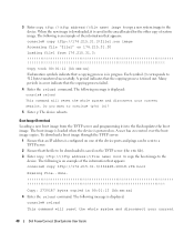
... Loading file1 from the TFTP server and programming it is displayed: console# reload This command will reset the whole system and disconnect your current 48 Dell PowerConnect 28xx Systems User Guide A period indicates that a copying process is displayed: console# reload This command ...will reset the whole system and disconnect your current session. To download a boot image through the TFTP server:...
... Loading file1 from the TFTP server and programming it is displayed: console# reload This command will reset the whole system and disconnect your current 48 Dell PowerConnect 28xx Systems User Guide A period indicates that a copying process is displayed: console# reload This command ...will reset the whole system and disconnect your current session. To download a boot image through the TFTP server:...
User's Guide
Page 56
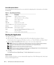
Reset All Counters Clears statistic counters. For information about recovering a lost password, see "Password Recovery. NOTE: The device can be managed via web interface only in the address bar and press . The Dell PowerConnect OpenManage™ Switch Administrator home page opens. Left arrow/... of configuring device information, and includes the following modes, based upon the access level assigned to the device, you : 56 Dell PowerConnect 28xx Systems User Guide Draw Creates statistics charts on page 49. 4 Click OK. For more information about management modes, see...
Reset All Counters Clears statistic counters. For information about recovering a lost password, see "Password Recovery. NOTE: The device can be managed via web interface only in the address bar and press . The Dell PowerConnect OpenManage™ Switch Administrator home page opens. Left arrow/... of configuring device information, and includes the following modes, based upon the access level assigned to the device, you : 56 Dell PowerConnect 28xx Systems User Guide Draw Creates statistics charts on page 49. 4 Click OK. For more information about management modes, see...
User's Guide
Page 59
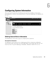
... → Asset in the tree view. Viewing Device Information The Asset page contains parameters for defining system parameters including security features, downloading device software, and resetting the device. To open the System page, click System in the tree view. Update with your book title 59 Figure 6-1. System 6 Defining General Device Information...
... → Asset in the tree view. Viewing Device Information The Asset page contains parameters for defining system parameters including security features, downloading device software, and resetting the device. To open the System page, click System in the tree view. Update with your book title 59 Figure 6-1. System 6 Defining General Device Information...
User's Guide
Page 60
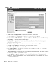
... the evening. • System Up Time - Specifies the device serial number. • Date (DD/MMM/YY) - Specifies the name of time since the last device reset. The system time is currently running. • MAC Address - Specifies the amount of the contact person. • System Location (0-159 Characters) - Specifies the current date...
... the evening. • System Up Time - Specifies the device serial number. • Date (DD/MMM/YY) - Specifies the name of time since the last device reset. The system time is currently running. • MAC Address - Specifies the amount of the contact person. • System Location (0-159 Characters) - Specifies the current date...
User's Guide
Page 62
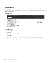
After the device is reset. Figure 6-4. A confirmation message displays. 3 Click OK. The device is reset, a prompt for a user name and password displays. 4 Enter a user name and password to reconnect to be reset from a remote location. For more information about saved Configuration files, see "Managing Files" on page 80. To open the Reset page, click System → General → Reset in the tree view. Resetting the Device The Reset page enables the device to the Web Interface. 62 Update with your book title Reset Resetting the Device 1 Open the Reset page 2 Click reset.
After the device is reset. Figure 6-4. A confirmation message displays. 3 Click OK. The device is reset, a prompt for a user name and password displays. 4 Enter a user name and password to reconnect to be reset from a remote location. For more information about saved Configuration files, see "Managing Files" on page 80. To open the Reset page, click System → General → Reset in the tree view. Resetting the Device The Reset page enables the device to the Web Interface. 62 Update with your book title Reset Resetting the Device 1 Open the Reset page 2 Click reset.
User's Guide
Page 93
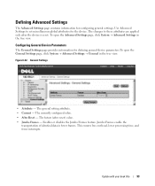
Use Advanced Settings to these attributes are applied only after reset) value. • Jumbo Frames - Configuring General Device Parameters The General Settings page provides information for defining general device parameters.To ... processing time, and fewer interrupts. General Settings • Attribute - The currently configured value. • After Reset - The general setting attribute. • Current - The future (after the device is reset. Enables or disables the Jumbo Frames feature. The changes to set miscellaneous global attributes for configuring general settings. ...
Use Advanced Settings to these attributes are applied only after reset) value. • Jumbo Frames - Configuring General Device Parameters The General Settings page provides information for defining general device parameters.To ... processing time, and fewer interrupts. General Settings • Attribute - The currently configured value. • After Reset - The general setting attribute. • Current - The future (after the device is reset. Enables or disables the Jumbo Frames feature. The changes to set miscellaneous global attributes for configuring general settings. ...
User's Guide
Page 100
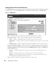
The port number for specific ports. Multiple Host - The possible field values are activated, or the device is reset. • Traps - Forwards the packets from any unlearned source. Discard - Discards the packet from an unknown source, however, the MAC address is the default value. - ...
The port number for specific ports. Multiple Host - The possible field values are activated, or the device is reset. • Traps - Forwards the packets from any unlearned source. Discard - Discards the packet from an unknown source, however, the MAC address is the default value. - ...
User's Guide
Page 109
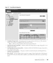
... Green Ethernet) is on or off for the device ports. • Link Short-Reach Energy Saving Mode - The percentage of energy saved since the last reset. For example, a Power Saving value of 14% indicates that just 86% of the power that would normally be used . This amount is on or off...
... Green Ethernet) is on or off for the device ports. • Link Short-Reach Energy Saving Mode - The percentage of energy saved since the last reset. For example, a Power Saving value of 14% indicates that just 86% of the power that would normally be used . This amount is on or off...

User's Guide
Page 118
... time. Identifies the Bridge priority and MAC address. • Root Bridge ID - The cost of time that have occurred since the bridge was initialized or reset, and the last topographic change occurred. The time is 2 seconds. • Max Age (6-40) - Modifying STP Global Parameters 1 Open the STP Global Settings page. 2 Define...
... time. Identifies the Bridge priority and MAC address. • Root Bridge ID - The cost of time that have occurred since the bridge was initialized or reset, and the last topographic change occurred. The time is 2 seconds. • Max Age (6-40) - Modifying STP Global Parameters 1 Open the STP Global Settings page. 2 Define...
User's Guide
Page 184
... Quality of Service, 147, 179 Queue, 151 R RADIUS, 71-73, 179 Rapid Spanning Tree Protocol, 180 RDP, 179 Remote Authentication Dial- In User Service, 179 Reset, 62-64 RMON, 144, 179 RSTP, 15, 180 Running Configuration file, 80 RVSP, 180 S Security, 69, 95 Simple Network Management Protocol, 74, 180 SNMP, 74...
... Quality of Service, 147, 179 Queue, 151 R RADIUS, 71-73, 179 Rapid Spanning Tree Protocol, 180 RDP, 179 Remote Authentication Dial- In User Service, 179 Reset, 62-64 RMON, 144, 179 RSTP, 15, 180 Running Configuration file, 80 RVSP, 180 S Security, 69, 95 Simple Network Management Protocol, 74, 180 SNMP, 74...


