
User's Guide
Page 3
Contents 1 Introduction 9 System Description 9 PowerConnect 2808 9 PowerConnect 2816 9 PowerConnect 2824 10 PowerConnect 2848 10 Summary of PowerConnect Models 11 Features 11 General Features 11 MAC Address Supported Features 13 Layer 2 Features 13 VLAN Supported Features 14...Switch Management Features 16 2 Hardware Description 17 Switch Port Configurations 17 PowerConnect 28xx Front and Back Panel Port Description 17 Physical Dimensions 21 LED Definitions 21 Power LED 22 Managed Mode LED 22 Fan LED (2824/2848 only 22 Port LEDs 22 Managed Mode Button 23 Switch Ventilation...
Contents 1 Introduction 9 System Description 9 PowerConnect 2808 9 PowerConnect 2816 9 PowerConnect 2824 10 PowerConnect 2848 10 Summary of PowerConnect Models 11 Features 11 General Features 11 MAC Address Supported Features 13 Layer 2 Features 13 VLAN Supported Features 14...Switch Management Features 16 2 Hardware Description 17 Switch Port Configurations 17 PowerConnect 28xx Front and Back Panel Port Description 17 Physical Dimensions 21 LED Definitions 21 Power LED 22 Managed Mode LED 22 Fan LED (2824/2848 only 22 Port LEDs 22 Managed Mode Button 23 Switch Ventilation...

User's Guide
Page 11
... active, but it prevents users from making configuration changes by traffic competing for additional incoming traffic. PowerConnect Models Model PowerConnect 2808 PowerConnect 2816 PowerConnect 2824 PowerConnect 2848 Copper Ports/ RJ-45 Connectors Optical Ports/ GbE 8 built-in 10/100/1000 Base-T ports... Features General Features Management Modes The device supports the following table summarizes the PowerConnect models. Fans baud rate is unavailable for the same egress port resources. Table 1-1. Dell PowerConnect 28xx Systems User Guide 11 Summary of the queue.
... active, but it prevents users from making configuration changes by traffic competing for additional incoming traffic. PowerConnect Models Model PowerConnect 2808 PowerConnect 2816 PowerConnect 2824 PowerConnect 2848 Copper Ports/ RJ-45 Connectors Optical Ports/ GbE 8 built-in 10/100/1000 Base-T ports... Features General Features Management Modes The device supports the following table summarizes the PowerConnect models. Fans baud rate is unavailable for the same egress port resources. Table 1-1. Dell PowerConnect 28xx Systems User Guide 11 Summary of the queue.

User's Guide
Page 19
... An SFP port for fiber connection. For more information about management modes and transitioning between management modes and to indicate the port status. Dell PowerConnect 28xx Systems User Guide 19 There are determined by the physical connection used at any one time. On the front panel is used on ...to transition between them, see "Management Modes" on or not. The Fan LED indicates the device fan operations status, and the Power LED on the front panel indicates whether the device is powered on page 49. PowerConnect 2824 Front Panel On the front panel there are 24 ports which ...
... An SFP port for fiber connection. For more information about management modes and transitioning between management modes and to indicate the port status. Dell PowerConnect 28xx Systems User Guide 19 There are determined by the physical connection used at any one time. On the front panel is used on ...to transition between them, see "Management Modes" on or not. The Fan LED indicates the device fan operations status, and the Power LED on the front panel indicates whether the device is powered on page 49. PowerConnect 2824 Front Panel On the front panel there are 24 ports which ...

User's Guide
Page 20
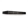
PowerConnect 2848 Front Panel On the front panel there are 48 ports, which are LEDs to right. NOTE: Only one time....Pair (TP) copper cabling. • An SFP port for fiber connection. NOTE: The system can be disabled. The Fan LED indicates the device fan operations status, and the Power LED on the front panel indicates whether the device is the Managed Mode LED which offers high... and 48, for swappable optical transceiver, which indicates the Ethernet switch operational status and the management mode. A Mode push- 20 Dell PowerConnect 28xx Systems User Guide Figure 2-6.
PowerConnect 2848 Front Panel On the front panel there are 48 ports, which are LEDs to right. NOTE: Only one time....Pair (TP) copper cabling. • An SFP port for fiber connection. NOTE: The system can be disabled. The Fan LED indicates the device fan operations status, and the Power LED on the front panel indicates whether the device is the Managed Mode LED which offers high... and 48, for swappable optical transceiver, which indicates the Ethernet switch operational status and the management mode. A Mode push- 20 Dell PowerConnect 28xx Systems User Guide Figure 2-6.

User's Guide
Page 21
...) • Depth - 255 mm (10.04 in.) LED Definitions The front panel contains LEDs that indicate the status of the PowerConnect 2848 device. button, located on the right side on the side panel. For more information about management modes and transitioning between management modes ... 330 mm (12.992 in.) • Depth - 230.50 mm (9.075 in.) The PowerConnect 2848 switch has the following figure illustrates the back panel of links, power supply, fan status, and Managed Mode status. The back panel contains an AC Power Supply Interface. Dell PowerConnect 28xx Systems User Guide 21
...) • Depth - 255 mm (10.04 in.) LED Definitions The front panel contains LEDs that indicate the status of the PowerConnect 2848 device. button, located on the right side on the side panel. For more information about management modes and transitioning between management modes ... 330 mm (12.992 in.) • Depth - 230.50 mm (9.075 in.) The PowerConnect 2848 switch has the following figure illustrates the back panel of links, power supply, fan status, and Managed Mode status. The back panel contains an AC Power Supply Interface. Dell PowerConnect 28xx Systems User Guide 21

User's Guide
Page 22
.... The following figure illustrates the RJ-45 10/100/1000BASE-T LEDs. 22 Dell PowerConnect 28xx Systems User Guide Power LED Indications LED Color Green Solid Off Description The switch is indicated on . Fan LED (2824/2848 only) On the PowerConnect 2824 and PowerConnect 2848 front panel there is a Managed Mode LED monitoring the switch node as well...
.... The following figure illustrates the RJ-45 10/100/1000BASE-T LEDs. 22 Dell PowerConnect 28xx Systems User Guide Power LED Indications LED Color Green Solid Off Description The switch is indicated on . Fan LED (2824/2848 only) On the PowerConnect 2824 and PowerConnect 2848 front panel there is a Managed Mode LED monitoring the switch node as well...

User's Guide
Page 23
... on the front panel. The PowerConnect 2808 and PowerConnect 2816 devices have no internal fans. Figure 2-9. The port is established. No link is linked at either 10 or 100 Mbps. The port is transmitting or receiving data at 10 or 100 Mbps. Dell PowerConnect 28xx Systems User Guide 23 Table...-based 10/100/1000BASE-T LEDs The RJ-45 LED indications are described in Full Duplex mode. Switch Ventilation Fan The PowerConnect 2848 switch has three fans and the PowerConnect 2824 switch has one fan for at 1000 Mbps. The port is linked at least 7 seconds. Managed Mode Button The...
... on the front panel. The PowerConnect 2808 and PowerConnect 2816 devices have no internal fans. Figure 2-9. The port is established. No link is linked at either 10 or 100 Mbps. The port is transmitting or receiving data at 10 or 100 Mbps. Dell PowerConnect 28xx Systems User Guide 23 Table...-based 10/100/1000BASE-T LEDs The RJ-45 LED indications are described in Full Duplex mode. Switch Ventilation Fan The PowerConnect 2848 switch has three fans and the PowerConnect 2824 switch has one fan for at 1000 Mbps. The port is linked at least 7 seconds. Managed Mode Button The...

