Getting Started Guide
Page 11
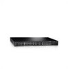
NOTE: Do not connect the power cable to a power source in the steps detailed in Starting and Configuring the Device. Getting Started Guide 9 You will connect the device to a grounded AC outlet at this time. After you have connected ... device to a power source, confirm that the device is connected and operating correctly by examining the LEDs on the back panel. Back-Panel Power Connectors PowerConnect Switch Rear View Power Connector Connect the device to the AC power connector on the front panel. Figure 1-4. Figure 1-3. Mounting Device on Wall Drilled Holes...
NOTE: Do not connect the power cable to a power source in the steps detailed in Starting and Configuring the Device. Getting Started Guide 9 You will connect the device to a grounded AC outlet at this time. After you have connected ... device to a power source, confirm that the device is connected and operating correctly by examining the LEDs on the back panel. Back-Panel Power Connectors PowerConnect Switch Rear View Power Connector Connect the device to the AC power connector on the front panel. Figure 1-4. Figure 1-3. Mounting Device on Wall Drilled Holes...

Getting Started Guide
Page 12
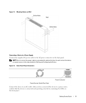
...Initial Configuration NOTE: The initial configuration uses the following information from the Dell Support website at support.dell.com. Starting and Configuring the Device NOTE: The device is designed...the system specific configuration. To use the management functions, refer the configuration options and details in the User's Guide. A power-on the enclosed CD. To begin using ... and subnet mask (255.255.255.0). • The PowerConnect device booted successfully. NOTE: Obtain the following assumptions: • The PowerConnect device is loaded into RAM. NOTE: It is recommended that...
...Initial Configuration NOTE: The initial configuration uses the following information from the Dell Support website at support.dell.com. Starting and Configuring the Device NOTE: The device is designed...the system specific configuration. To use the management functions, refer the configuration options and details in the User's Guide. A power-on the enclosed CD. To begin using ... and subnet mask (255.255.255.0). • The PowerConnect device booted successfully. NOTE: Obtain the following assumptions: • The PowerConnect device is loaded into RAM. NOTE: It is recommended that...
Readme
Page 3
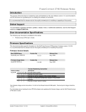
... notes, or additional assistance, see the Dell PowerConnect 2748 User's Guide. Denotes a scheduled maintenance release of this product. The boot prom image should be 1.0.0.3. For information about loading the boot PROM software and updating the firmware image, see the Dell Support website at support.dell.com. Firmware Version Details Boot PROM Name bryant48_boot-10003.rfb Version...
... notes, or additional assistance, see the Dell PowerConnect 2748 User's Guide. Denotes a scheduled maintenance release of this product. The boot prom image should be 1.0.0.3. For information about loading the boot PROM software and updating the firmware image, see the Dell Support website at support.dell.com. Firmware Version Details Boot PROM Name bryant48_boot-10003.rfb Version...

User's Guide
Page 33
...is detected, the POST process fails and the Managed Mode LED indicator turns solid amber (PowerConnect 2748). If you may stop there. If you desire to manage the device, you will... cabling you require basic connectivity and do not want to follow the instructions detailed here in the PowerConnect 2708/2716/2724 switch the Managed Mode LED indicator turns solid red. If...or advanced network connectivity with web-managed features and funtionality. 4 Starting and Configuring the Dell™ PowerConnect™ 27XX NOTE: Before proceeding, read the release notes for this chapter. Viewing ...
...is detected, the POST process fails and the Managed Mode LED indicator turns solid amber (PowerConnect 2748). If you may stop there. If you desire to manage the device, you will... cabling you require basic connectivity and do not want to follow the instructions detailed here in the PowerConnect 2708/2716/2724 switch the Managed Mode LED indicator turns solid red. If...or advanced network connectivity with web-managed features and funtionality. 4 Starting and Configuring the Dell™ PowerConnect™ 27XX NOTE: Before proceeding, read the release notes for this chapter. Viewing ...
User's Guide
Page 69
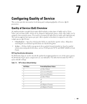
... (VPT) and DSCP (DiffServ Code Point). After a packet is an improved traffic flow for defining and configuring Quality of the egress queues. The table below details the VPT to Queue Default Settings CoS Value 0 1 2 3 4 5 6 7 Forwarding Queue Values q2 (Best Effort) q1 (Lowest Priority) q1 (Lowest Priority) q2 (Best Effort) q3 q3...
... (VPT) and DSCP (DiffServ Code Point). After a packet is an improved traffic flow for defining and configuring Quality of the egress queues. The table below details the VPT to Queue Default Settings CoS Value 0 1 2 3 4 5 6 7 Forwarding Queue Values q2 (Best Effort) q1 (Lowest Priority) q1 (Lowest Priority) q2 (Best Effort) q3 q3...
