User's Guide
Page 3
... 9 Mounting Kit Instructions 10 Installing the Switch on a Flat Surface 10 Installing the Switch in a Rack 10 Installing the Switch on a Wall 11 Technical Information 12 2 Troubleshooting 3 Getting Help Technical Assistance 17 Online Services 17 AutoTech Service 18 Automated Order-Status Service 18 Technical Support Service 19 Dell Enterprise Training and Certification 19 Problems...
... 9 Mounting Kit Instructions 10 Installing the Switch on a Flat Surface 10 Installing the Switch in a Rack 10 Installing the Switch on a Wall 11 Technical Information 12 2 Troubleshooting 3 Getting Help Technical Assistance 17 Online Services 17 AutoTech Service 18 Automated Order-Status Service 18 Technical Support Service 19 Dell Enterprise Training and Certification 19 Problems...
User's Guide
Page 4
Figure 1-6. Figure 1-2. Figure 1-5. Table 2-1. Figure 1-4. Tag-Based Prioritization 9 Specifications 12 Basic Troubleshooting 15 4 Contents Table 1-2. Figure 1-3. PowerConnect 2608 7 PowerConnect 2616 7 PowerConnect 2624 8 Cascading Switches 9 Brackets for Rack Installation 11 Brackets for Warranty Repair or Credit 19 Before You Call 20 Contacting Dell 20 Figures Figure 1-1. Returning Items for Wall Installation 12 Tables Table 1-1.
Figure 1-6. Figure 1-2. Figure 1-5. Table 2-1. Figure 1-4. Tag-Based Prioritization 9 Specifications 12 Basic Troubleshooting 15 4 Contents Table 1-2. Figure 1-3. PowerConnect 2608 7 PowerConnect 2616 7 PowerConnect 2624 8 Cascading Switches 9 Brackets for Rack Installation 11 Brackets for Warranty Repair or Credit 19 Before You Call 20 Contacting Dell 20 Figures Figure 1-1. Returning Items for Wall Installation 12 Tables Table 1-1.
User's Guide
Page 5
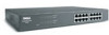
... chassis • Internal power supply Package Contents Before you install a switch, verify that your package contains the following features: • 10/100/1000-Mbps switch ports - 8 ports (PowerConnect 2608) - 16 ports (PowerConnect 2616) - 24 ports, including one combination RJ-45/small form factor (SFP) port (PowerConnect 2624) • Complies with IEEE 802.3 10Base-T, IEEE 802.3u...
... chassis • Internal power supply Package Contents Before you install a switch, verify that your package contains the following features: • 10/100/1000-Mbps switch ports - 8 ports (PowerConnect 2608) - 16 ports (PowerConnect 2616) - 24 ports, including one combination RJ-45/small form factor (SFP) port (PowerConnect 2624) • Complies with IEEE 802.3 10Base-T, IEEE 802.3u...
User's Guide
Page 6
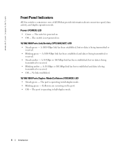
...Mbps link has been established and data is powered on . 10/100/1000 Ports Link/Activity (SPD/LNK/ACT) LED • Steady green - The switch is being transmitted or received. • Blinking green - A 10-Mbps or 100-Mbps link has been established, but no data is not powered on ... A 10-Mbps or 100-Mbps link has been established and data is operating in half-duplex mode. 6 Introduction www.dell.com | support.dell.com Front Panel Indicators All 26xx switches contain two rows of LEDS that provide information about connection speed, data activity, and duplex operation mode. The port is ...
...Mbps link has been established and data is powered on . 10/100/1000 Ports Link/Activity (SPD/LNK/ACT) LED • Steady green - The switch is being transmitted or received. • Blinking green - A 10-Mbps or 100-Mbps link has been established, but no data is not powered on ... A 10-Mbps or 100-Mbps link has been established and data is operating in half-duplex mode. 6 Introduction www.dell.com | support.dell.com Front Panel Indicators All 26xx switches contain two rows of LEDS that provide information about connection speed, data activity, and duplex operation mode. The port is ...
User's Guide
Page 8
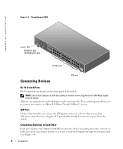
... is used for connecting devices at 1000-Mbps Gigabit Ethernet speed. and half-duplex modes automatically. www.dell.com | support.dell.com Figure 1-3. However, using the SFP port disables the RJ-45 connector of the switch. PowerConnect 2624 power LED FDX/HDX LEDs SPD/LNK/ACT LEDs RJ-45 ports Connecting Devices SFP port...
... is used for connecting devices at 1000-Mbps Gigabit Ethernet speed. and half-duplex modes automatically. www.dell.com | support.dell.com Figure 1-3. However, using the SFP port disables the RJ-45 connector of the switch. PowerConnect 2624 power LED FDX/HDX LEDs SPD/LNK/ACT LEDs RJ-45 ports Connecting Devices SFP port...
User's Guide
Page 9
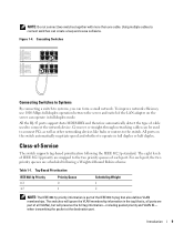
... destination port. Class-of IEEE 802.1p priority are mapped to systems, you can create a loop and cause collisions. The switches will preserve the full tag information-including packet priority and VLAN ID- To improve network efficiency, use 1000-Mbps full-duplex operation... between the server and switch if the LAN adapter on the switch automatically negotiate speed and whether to connect switches can form a small network. The eight levels of -Service The switch supports tag-based prioritization following a Weighted Round Robin scheme. Figure...
... destination port. Class-of IEEE 802.1p priority are mapped to systems, you can create a loop and cause collisions. The switches will preserve the full tag information-including packet priority and VLAN ID- To improve network efficiency, use 1000-Mbps full-duplex operation... between the server and switch if the LAN adapter on the switch automatically negotiate speed and whether to connect switches can form a small network. The eight levels of -Service The switch supports tag-based prioritization following a Weighted Round Robin scheme. Figure...
User's Guide
Page 10
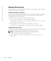
... the following steps: 1 Use the supplied screws to attach a mounting bracket to keep the switch from slipping. The rubber feet are optional, but are 48.3 cm (19 inches). Installing the Switch in a Rack The switch can be installed in Dell PowerEdge™ racks, which are recommended to each marked location on any appropriate level...
... the following steps: 1 Use the supplied screws to attach a mounting bracket to keep the switch from slipping. The rubber feet are optional, but are 48.3 cm (19 inches). Installing the Switch in a Rack The switch can be installed in Dell PowerEdge™ racks, which are recommended to each marked location on any appropriate level...
User's Guide
Page 11
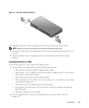
...NOTE: Additional screws are provided for racks that the mounting point meets the following steps: 1 Ensure that have threaded mounting holes. 3 Position the switch in the rack and align the holes in the mounting bracket with the holes in direct sunlight. • The location must not be within 2...electrical cabling located directly behind the unit. • The power cable must be ventilated to prevent heat buildup. • Do not locate the switch where there may be located in the rack. 4 Insert and tighten two screws appropriate for Rack Installation 2 Install the cage nuts onto the...
...NOTE: Additional screws are provided for racks that the mounting point meets the following steps: 1 Ensure that have threaded mounting holes. 3 Position the switch in the rack and align the holes in the mounting bracket with the holes in direct sunlight. • The location must not be within 2...electrical cabling located directly behind the unit. • The power cable must be ventilated to prevent heat buildup. • Do not locate the switch where there may be located in the rack. 4 Insert and tighten two screws appropriate for Rack Installation 2 Install the cage nuts onto the...
User's Guide
Page 12
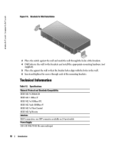
one SFP connector available on 24-port switch Power Supply 100-240 VAC/5060 Hz universal input 12 Introduction Technical Information Table 1-2. Specifications Network Protocol and Standards Compatibility IEEE 802.3 CSMA/...-TX IEEE 802.3z/ab 1000Base-T IEEE 802.3x Flow Control IEEE 802.3p Priority Interface RJ-45 connectors; www.dell.com | support.dell.com Figure 1-6. Brackets for Wall Installation 3 Place the switch against the wall and mark the wall through the holes of the brackets. 4 Drill holes in the wall for the...
one SFP connector available on 24-port switch Power Supply 100-240 VAC/5060 Hz universal input 12 Introduction Technical Information Table 1-2. Specifications Network Protocol and Standards Compatibility IEEE 802.3 CSMA/...-TX IEEE 802.3z/ab 1000Base-T IEEE 802.3x Flow Control IEEE 802.3p Priority Interface RJ-45 connectors; www.dell.com | support.dell.com Figure 1-6. Brackets for Wall Installation 3 Place the switch against the wall and mark the wall through the holes of the brackets. 4 Drill holes in the wall for the...
User's Guide
Page 13
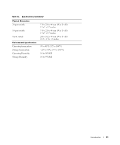
Table 1-2. Specifications (continued) Physical Dimensions 24-port switch 16-port switch 8-port switch Environmental Specifications Operating temperature Storage temperature Operating Humidity Storage Humidity 330 x 228 x 44 mm (W x D x H) 13 x 9 x 1.7 inches 330 x 228 x 44 mm (W x D x H) 13 x 9 x 1.7 inches 266 x 162 x 44 mm (W x D x H) 10.5 x 6.4 x 1.7 inches 0º to 40ºC (32º to 104ºF) -20º to 70ºC (-4º to 158ºF) 10 to 90% RH 10 to 95% RH Introduction 13
Table 1-2. Specifications (continued) Physical Dimensions 24-port switch 16-port switch 8-port switch Environmental Specifications Operating temperature Storage temperature Operating Humidity Storage Humidity 330 x 228 x 44 mm (W x D x H) 13 x 9 x 1.7 inches 330 x 228 x 44 mm (W x D x H) 13 x 9 x 1.7 inches 266 x 162 x 44 mm (W x D x H) 10.5 x 6.4 x 1.7 inches 0º to 40ºC (32º to 104ºF) -20º to 70ºC (-4º to 158ºF) 10 to 90% RH 10 to 95% RH Introduction 13
User's Guide
Page 15
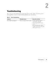
Basic Troubleshooting Problem Probable Cause Power LED is no power to the switch. Ensure that the switch is securely connected to the switch and to a properly functioning and active power source. Corrective Action Confirm that the power cable is connected to a power source. Table 2-1 describes general cluster problems you may encounter and the probable causes and solutions. There is not lighted. 2 Troubleshooting This section provides troubleshooting information for your switch. Troubleshooting 15 Table 2-1.
Basic Troubleshooting Problem Probable Cause Power LED is no power to the switch. Ensure that the switch is securely connected to the switch and to a properly functioning and active power source. Corrective Action Confirm that the power cable is connected to a power source. Table 2-1 describes general cluster problems you may encounter and the probable causes and solutions. There is not lighted. 2 Troubleshooting This section provides troubleshooting information for your switch. Troubleshooting 15 Table 2-1.
User's Guide
Page 16
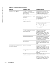
...dell.com | support.dell.com Table 2-1. Basic Troubleshooting (continued) Problem Probable Cause Link LED is damaged or not properly terminated. Link speed LED indicates a lower Incorrect cable grade. Reconnect the connector for the affected link to the switch or the attached device. The cable is not securely connected to a different switch... lighted. Ensure that all 10Base-T and 100Base-T links, or Category 5e for all devices connected to the switch and use a shorter cable. The cable's maximum distance has been exceeded. 10Base-T, 100Base-T, and 1000Base-T cables...
...dell.com | support.dell.com Table 2-1. Basic Troubleshooting (continued) Problem Probable Cause Link LED is damaged or not properly terminated. Link speed LED indicates a lower Incorrect cable grade. Reconnect the connector for the affected link to the switch or the attached device. The cable is not securely connected to a different switch... lighted. Ensure that all 10Base-T and 100Base-T links, or Category 5e for all devices connected to the switch and use a shorter cable. The cable's maximum distance has been exceeded. 10Base-T, 100Base-T, and 1000Base-T cables...
User's Guide
Page 17
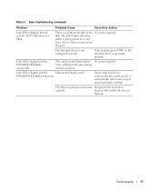
The LED blinks only when traffic is being passed to the port. No action required. Ensure that any devices connected to the switch are set port speed and duplex settings. Table 2-1. This can be normal link activity. Basic Troubleshooting (continued) Problem Probable Cause Corrective Action Link LED is ...
The LED blinks only when traffic is being passed to the port. No action required. Ensure that any devices connected to the switch are set port speed and duplex settings. Table 2-1. This can be normal link activity. Basic Troubleshooting (continued) Problem Probable Cause Corrective Action Link LED is ...


