User's Guide
Page 5
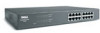
...rackmountable and wallmountable, standard 1U chassis • Internal power supply Package Contents Before you install a switch, verify that your package contains the following features: • 10/100/1000-Mbps switch ports - 8 ports (PowerConnect 2608) - 16 ports (PowerConnect 2616) - 24 ports, including one combination RJ-45/...-T • Tag-based IEEE 802.1p Class-of 16- and 24-port switches • PowerConnect 26xx Switches CD • AC power cord Introduction 5 1 Introduction Dell™ PowerConnect™ 26xx switches provide 10/100/1000-Mbps Gigabit Ethernet connectivity.
...rackmountable and wallmountable, standard 1U chassis • Internal power supply Package Contents Before you install a switch, verify that your package contains the following features: • 10/100/1000-Mbps switch ports - 8 ports (PowerConnect 2608) - 16 ports (PowerConnect 2616) - 24 ports, including one combination RJ-45/...-T • Tag-based IEEE 802.1p Class-of 16- and 24-port switches • PowerConnect 26xx Switches CD • AC power cord Introduction 5 1 Introduction Dell™ PowerConnect™ 26xx switches provide 10/100/1000-Mbps Gigabit Ethernet connectivity.
User's Guide
Page 10
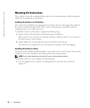
...(2 inches) on each marked location on a flat surface, complete the following steps: 1 Use the supplied screws to attach a mounting bracket to each side of the switch (see Figure 1-5). 10 Introduction To ...in most other standard 19-inch racks and most telco two-post racks. www.dell.com | support.dell.com Mounting Kit Instructions These switches come with mounting brackets and screws for rackmounting ... rack, complete the following steps: 1 Set the switch on the flat surface and check for power cable clearance. 2 Attach rubber feet on the switch if you are recommended to keep the switch...
...(2 inches) on each marked location on a flat surface, complete the following steps: 1 Use the supplied screws to attach a mounting bracket to each side of the switch (see Figure 1-5). 10 Introduction To ...in most other standard 19-inch racks and most telco two-post racks. www.dell.com | support.dell.com Mounting Kit Instructions These switches come with mounting brackets and screws for rackmounting ... rack, complete the following steps: 1 Set the switch on the flat surface and check for power cable clearance. 2 Attach rubber feet on the switch if you are recommended to keep the switch...
User's Guide
Page 11
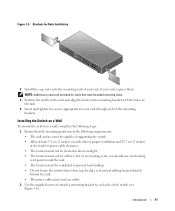
... Do not locate the switch where there may be data or electrical cabling located directly behind the unit. • The power cable must reach an outlet. 2 Use the supplied screws to attach a mounting bracket to each of the mounting brackets. Introduction 11 Figure 1-5. Brackets for your rack through each...the switch. • Allow at least 5.1 cm (2 inches) on each side for proper ventilation and 12.7 cm (5 inches) at the back for power cable clearance. • The location must not be located in the rack. 4 Insert and tighten two screws appropriate for Rack Installation 2 Install the ...
... Do not locate the switch where there may be data or electrical cabling located directly behind the unit. • The power cable must reach an outlet. 2 Use the supplied screws to attach a mounting bracket to each of the mounting brackets. Introduction 11 Figure 1-5. Brackets for your rack through each...the switch. • Allow at least 5.1 cm (2 inches) on each side for proper ventilation and 12.7 cm (5 inches) at the back for power cable clearance. • The location must not be located in the rack. 4 Insert and tighten two screws appropriate for Rack Installation 2 Install the ...
User's Guide
Page 12
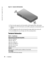
www.dell.com | support.dell.com Figure 1-6. one SFP connector available on 24-port switch Power Supply 100-240 VAC/5060 Hz universal input 12 Introduction Specifications Network Protocol and Standards Compatibility IEEE 802.3 CSMA/CD IEEE 802.3 10Base-T IEEE ... and mark the wall through the holes of the brackets. 4 Drill holes in the wall for the brackets and install the appropriate mounting hardware (not supplied). 5 Place the against the wall so that the bracket holes align with the holes in the wall. 6 Insert and tighten the screws through each of...
www.dell.com | support.dell.com Figure 1-6. one SFP connector available on 24-port switch Power Supply 100-240 VAC/5060 Hz universal input 12 Introduction Specifications Network Protocol and Standards Compatibility IEEE 802.3 CSMA/CD IEEE 802.3 10Base-T IEEE ... and mark the wall through the holes of the brackets. 4 Drill holes in the wall for the brackets and install the appropriate mounting hardware (not supplied). 5 Place the against the wall so that the bracket holes align with the holes in the wall. 6 Insert and tighten the screws through each of...


