User's Guide
Page 3
...Activity (SPD/LNK/ACT) LED (2324 only) . . . . . 7 Duplex Mode/Collisions (FDX/HDX) LED 7 Connecting Devices 9 RJ-45 Switch Ports 9 Connecting Switches to Each Other 9 Connecting Switches to Other Devices 9 Typical Deployments 10 Class-of-Service 10 Mounting Kit Instructions 11 Installing the... Switch on a Flat Surface 11 Installing the Switch in a Rack 11 Installing the Switch on a Wall 12 Technical Information 13 2 Troubleshooting 3 Getting Help Technical Assistance 19 Online...
...Activity (SPD/LNK/ACT) LED (2324 only) . . . . . 7 Duplex Mode/Collisions (FDX/HDX) LED 7 Connecting Devices 9 RJ-45 Switch Ports 9 Connecting Switches to Each Other 9 Connecting Switches to Other Devices 9 Typical Deployments 10 Class-of-Service 10 Mounting Kit Instructions 11 Installing the... Switch on a Flat Surface 11 Installing the Switch in a Rack 11 Installing the Switch on a Wall 12 Technical Information 13 2 Troubleshooting 3 Getting Help Technical Assistance 19 Online...
User's Guide
Page 4
Figure 1-3. Figure 1-4. Table 2-1. Figure 1-6. Figure 1-7. Figure 1-5. Figure 1-8. PowerConnect 2216 7 PowerConnect 2224 8 PowerConnect 2324 8 Cascading Switches 9 Small Workgroup 10 Large Workgroup 10 Brackets for Rack Installation 12 Brackets for Warranty Repair or Credit 21 Before You Call 22 Contacting Dell 22 Figures Figure 1-1. Product Information 21 Returning Items for Wall Installation 13 Tables Table 1-1. Table 1-2. Tag-Based Prioritization 11 Specifications 13 Basic Troubleshooting 15 4 Contents Figure 1-2.
Figure 1-3. Figure 1-4. Table 2-1. Figure 1-6. Figure 1-7. Figure 1-5. Figure 1-8. PowerConnect 2216 7 PowerConnect 2224 8 PowerConnect 2324 8 Cascading Switches 9 Small Workgroup 10 Large Workgroup 10 Brackets for Rack Installation 12 Brackets for Warranty Repair or Credit 21 Before You Call 22 Contacting Dell 22 Figures Figure 1-1. Product Information 21 Returning Items for Wall Installation 13 Tables Table 1-1. Table 1-2. Tag-Based Prioritization 11 Specifications 13 Basic Troubleshooting 15 4 Contents Figure 1-2.
User's Guide
Page 5
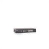
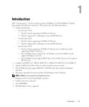
...ports • Auto MDI/MDIX • 8K MAC address entries supported Introduction 5 or half-duplex mode; Introduction Dell™ PowerConnect™ 22xx/23xx switches provide 10/100Base-T or 10/100/1000Base-T Gigabit plug-and-play Fast Ethernet connectivity. or half-duplex mode ...the 1000Base-T ports support full-duplex mode only. • The 10/100Base-T ports support PAUSE frames; The switches have the following features: • Product specifications - PowerConnect 2216 • Provides 16 ports supporting 10/100Base-T Ethernet. • All ports support full- and half-duplex...
...ports • Auto MDI/MDIX • 8K MAC address entries supported Introduction 5 or half-duplex mode; Introduction Dell™ PowerConnect™ 22xx/23xx switches provide 10/100Base-T or 10/100/1000Base-T Gigabit plug-and-play Fast Ethernet connectivity. or half-duplex mode ...the 1000Base-T ports support full-duplex mode only. • The 10/100Base-T ports support PAUSE frames; The switches have the following features: • Product specifications - PowerConnect 2216 • Provides 16 ports supporting 10/100Base-T Ethernet. • All ports support full- and half-duplex...
User's Guide
Page 6
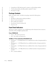
...; Blinking amber - The switch is not powered on . • Off - The switch is powered on . 10/100Base-T Ports Link/Activity (SPD/LNK/ACT) LED • Steady green - www.dell.com | support.dell.com • Comprehensive LED indicator panel to monitor overall switching condition • 19-inch...• Kit for 19-inch rack installation • Kit for wallmount installation • PowerConnect 22xx/23xx Switches CD • AC power cord Front Panel Indicators All 22xx/23xx switches contain two rows of LEDS that provide information about connection speed, data activity, and duplex...
...; Blinking amber - The switch is not powered on . • Off - The switch is powered on . 10/100Base-T Ports Link/Activity (SPD/LNK/ACT) LED • Steady green - www.dell.com | support.dell.com • Comprehensive LED indicator panel to monitor overall switching condition • 19-inch...• Kit for 19-inch rack installation • Kit for wallmount installation • PowerConnect 22xx/23xx Switches CD • AC power cord Front Panel Indicators All 22xx/23xx switches contain two rows of LEDS that provide information about connection speed, data activity, and duplex...
User's Guide
Page 9
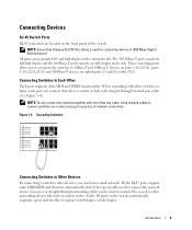
... form a small network. Using multiple cables to connect switches can be used to connect the network device. Crossover or straight-through twisted-pair cable (see Figure 1-4). Connecting Switches to 10Base-T and 100Base-T devices on ports 1-16 (2216), ports 1-24 (2224, 2324) and 1000Base-T devices... on uplink ports 25 and 26 on the front panel of network connectivity. These switching ports allow users to connect the switches to Each Other Each...
... form a small network. Using multiple cables to connect switches can be used to connect the network device. Crossover or straight-through twisted-pair cable (see Figure 1-4). Connecting Switches to 10Base-T and 100Base-T devices on ports 1-16 (2216), ports 1-24 (2224, 2324) and 1000Base-T devices... on uplink ports 25 and 26 on the front panel of network connectivity. These switching ports allow users to connect the switches to Each Other Each...
User's Guide
Page 10
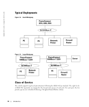
... two priority queues of -Service The switch supports tag-based prioritization following a Weighted Round Robin scheme. 10 Introduction www.dell.com | support.dell.com Typical Deployments Figure 1-5. For each port. The eight levels of IEEE 802.1p priority are scheduled following the IEEE 802.1p standard. Small Workgroup PowerConnect 2216, 2224, 2324 10/100Base-T PC...
... two priority queues of -Service The switch supports tag-based prioritization following a Weighted Round Robin scheme. 10 Introduction www.dell.com | support.dell.com Typical Deployments Figure 1-5. For each port. The eight levels of IEEE 802.1p priority are scheduled following the IEEE 802.1p standard. Small Workgroup PowerConnect 2216, 2224, 2324 10/100Base-T PC...
User's Guide
Page 11
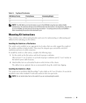
... wallmounting and rubber feet for proper ventilation. To install the switch on a flat surface, complete the following steps: 1 Set the switch on any appropriate level surface that is part of the chassis. Installing the Switch in Dell PowerEdge™ racks, which are rackmounting the switch. The rubber feet are optional, but will ignore the VLAN...
... wallmounting and rubber feet for proper ventilation. To install the switch on a flat surface, complete the following steps: 1 Set the switch on any appropriate level surface that is part of the chassis. Installing the Switch in Dell PowerEdge™ racks, which are rackmounting the switch. The rubber feet are optional, but will ignore the VLAN...
User's Guide
Page 12
...dell.com | support.dell.com To install the switch in a rack, complete the following steps: 1 Use the supplied screws to attach a mounting bracket to prevent heat buildup. 12 Introduction NOTE: Additional screws are provided for racks that the mounting point meets the following steps: 1 Ensure that have threaded mounting holes. 3 Position the switch... should any area heating vent point toward the unit. • The location must not be ventilated to each of the switch (see Figure 1-7). Brackets for power cable clearance. • The location must not be located in the rack. 4 ...
...dell.com | support.dell.com To install the switch in a rack, complete the following steps: 1 Use the supplied screws to attach a mounting bracket to prevent heat buildup. 12 Introduction NOTE: Additional screws are provided for racks that the mounting point meets the following steps: 1 Ensure that have threaded mounting holes. 3 Position the switch... should any area heating vent point toward the unit. • The location must not be ventilated to each of the switch (see Figure 1-7). Brackets for power cable clearance. • The location must not be located in the rack. 4 ...

User's Guide
Page 13
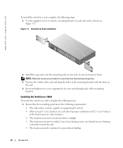
...• The power cable must reach an outlet. 2 Use the supplied screws to attach a mounting bracket to each of the switch (see Figure 1-8). Brackets for Wall Installation 3 Place the switch against the wall and mark the wall through the holes of the brackets. 4 Drill holes in the wall for the brackets... and install the appropriate mounting hardware (not supplied). 5 Place the switch against the wall so that the bracket holes align with the holes in the wall. 6 Insert and tighten the screws through each side of the...
...• The power cable must reach an outlet. 2 Use the supplied screws to attach a mounting bracket to each of the switch (see Figure 1-8). Brackets for Wall Installation 3 Place the switch against the wall and mark the wall through the holes of the brackets. 4 Drill holes in the wall for the brackets... and install the appropriate mounting hardware (not supplied). 5 Place the switch against the wall so that the bracket holes align with the holes in the wall. 6 Insert and tighten the screws through each side of the...

User's Guide
Page 15
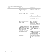
...15 Table 2-1 describes general cluster problems you may encounter and the probable causes and solutions. The cable is no power to the switch or the attached device. Ensure that the power cable is connected to a power source. Table 2-1. Corrective Action Confirm that the connectors... are fully inserted into the ports of the switch and the attached device. Basic Troubleshooting Problem Power LED is not lighted. Link LED is not lighted. Ensure that the switch is securely connected to the switch and to a properly functioning and active power source. Troubleshooting...
...15 Table 2-1 describes general cluster problems you may encounter and the probable causes and solutions. The cable is no power to the switch or the attached device. Ensure that the power cable is connected to a power source. Table 2-1. Corrective Action Confirm that the connectors... are fully inserted into the ports of the switch and the attached device. Basic Troubleshooting Problem Power LED is not lighted. Link LED is not lighted. Ensure that the switch is securely connected to the switch and to a properly functioning and active power source. Troubleshooting...
User's Guide
Page 16
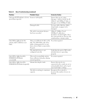
...the cables are configured to a 1000Base-T port (ports 25 and 26) on the PowerConnect 2324 switch. Try a known working cable. Move the connected device closer to a different switch port. 16 Troubleshooting Reconnect the connector for link lengths. The cable is operating properly. ... that the NIC on . A 10/100Base-T-capable device or 1000Base-T half-duplex device is powered on. Bad switch port. www.dell.com | support.dell.com Table 2-1. Basic Troubleshooting (continued) Problem Probable Cause The attached device is not configured correctly, or it is...
...the cables are configured to a 1000Base-T port (ports 25 and 26) on the PowerConnect 2324 switch. Try a known working cable. Move the connected device closer to a different switch port. 16 Troubleshooting Reconnect the connector for link lengths. The cable is operating properly. ... that the NIC on . A 10/100Base-T-capable device or 1000Base-T half-duplex device is powered on. Bad switch port. www.dell.com | support.dell.com Table 2-1. Basic Troubleshooting (continued) Problem Probable Cause The attached device is not configured correctly, or it is...
User's Guide
Page 17
...the port. Basic Troubleshooting (continued) Problem Probable Cause Corrective Action Link speed LED indicates a lower Incorrect cable grade. Test any devices connected to the switch and use a shorter cable. The LED blinks only when traffic is being passed to or sent from a device that you are set to be... normal link activity. Move the connected device closer to the switch are using Category 5 cable or better for all 10Base-T and 100Base-T links, or Category 5e for link lengths. link. decrease the number of...
...the port. Basic Troubleshooting (continued) Problem Probable Cause Corrective Action Link speed LED indicates a lower Incorrect cable grade. Test any devices connected to the switch and use a shorter cable. The LED blinks only when traffic is being passed to or sent from a device that you are set to be... normal link activity. Move the connected device closer to the switch are using Category 5 cable or better for all 10Base-T and 100Base-T links, or Category 5e for link lengths. link. decrease the number of...
User's Guide
Page 25
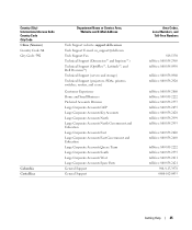
... Colombia Costa Rica Department Name or Service Area, Website and E-Mail Address Tech Support website: support.dell.com.cn Tech Support E-mail: cn_support@dell.com Tech Support Fax Technical Support (Dimension™ and Inspiron™) Technical Support (OptiPlex™, Latitude™...;, and Dell Precision™) Technical Support (servers and storage) Technical Support (projectors, PDAs, printers, switches, routers, and so on) Customer Experience Home and Small Business Preferred Accounts Division Large...
... Colombia Costa Rica Department Name or Service Area, Website and E-Mail Address Tech Support website: support.dell.com.cn Tech Support E-mail: cn_support@dell.com Tech Support Fax Technical Support (Dimension™ and Inspiron™) Technical Support (OptiPlex™, Latitude™...;, and Dell Precision™) Technical Support (servers and storage) Technical Support (projectors, PDAs, printers, switches, routers, and so on) Customer Experience Home and Small Business Preferred Accounts Division Large...
Technical Specifications Update for the Dell™ PowerConnect™ 2200/2300 Series Ethernet Switches
Page 1
... received. • Off - Where any differences exist in the specifications or procedures between the two documents, the information in the Dell PowerConnect 2216/2224/2324 Switches User's Guide. All ports support full- Product Specifications • PowerConnect 2216 - All ports support full- or half-duplex mode; The 10/100Base-T ports support PAUSE frames; Front-Panel Indicators 1000Base...
... received. • Off - Where any differences exist in the specifications or procedures between the two documents, the information in the Dell PowerConnect 2216/2224/2324 Switches User's Guide. All ports support full- Product Specifications • PowerConnect 2216 - All ports support full- or half-duplex mode; The 10/100Base-T ports support PAUSE frames; Front-Panel Indicators 1000Base...
Technical Specifications Update for the Dell™ PowerConnect™ 2200/2300 Series Ethernet Switches
Page 2
... and trade names other than its own. Trademarks used in the Dell PowerConnect 2216/2224/2324 Switches User's Guide. Printed in this text: Dell, the DELL logo, and PowerConnect are trademarks of Dell Inc. www.dell.com | support.dell.com K5672A00.fm Page 2 Friday, February 20, 2004 3:45 PM... and names or their products. is duplex capable devices to ports connected to change without the written permission of Dell Inc. PowerConnect 2324 switch. Dell Inc. Other trademarks and trade names may be used in China. Reproduction in any proprietary interest in this document...
... and trade names other than its own. Trademarks used in the Dell PowerConnect 2216/2224/2324 Switches User's Guide. Printed in this text: Dell, the DELL logo, and PowerConnect are trademarks of Dell Inc. www.dell.com | support.dell.com K5672A00.fm Page 2 Friday, February 20, 2004 3:45 PM... and names or their products. is duplex capable devices to ports connected to change without the written permission of Dell Inc. PowerConnect 2324 switch. Dell Inc. Other trademarks and trade names may be used in China. Reproduction in any proprietary interest in this document...


