
Hardware Maintenance Manual
Page 4
PS6500 Hardware Maintenance 4 Maintaining Power Supply and Cooling Modules 4-1 Power Supply and Cooling Module LEDs...4-1 Power Supply and Cooling Module Status ...4-2 Array Behavior When a Power Supply Fails ...4-2 Power Requirements and Recommendations...4-3 Removing a Power Supply and Cooling Module...4-3 Installing a Power Supply and Cooling Module ...4-4 5 Maintaining Channel Cards...5-1 Channel Card LEDs ...5-1 Channel Card Status ...5-2 Array Behavior When a Channel Card Fails...5-2 Channel Card Handling Requirements...5-3 Replacing a Channel Card...
PS6500 Hardware Maintenance 4 Maintaining Power Supply and Cooling Modules 4-1 Power Supply and Cooling Module LEDs...4-1 Power Supply and Cooling Module Status ...4-2 Array Behavior When a Power Supply Fails ...4-2 Power Requirements and Recommendations...4-3 Removing a Power Supply and Cooling Module...4-3 Installing a Power Supply and Cooling Module ...4-4 5 Maintaining Channel Cards...5-1 Channel Card LEDs ...5-1 Channel Card Status ...5-2 Array Behavior When a Channel Card Fails...5-2 Channel Card Handling Requirements...5-3 Replacing a Channel Card...
Hardware Maintenance Manual
Page 5
...a network is beyond its scope. However, it may be useful to maintain the PS6500 storage array hardware, including disks, channel cards, EIP card, control modules, and power supply and cooling modules. Preface This manual describes how to understand: • Basic networking ...concepts • Current network environment • Disk storage space requirements • RAID configurations • Disk storage management Note: Although this manual provides examples of Dell EqualLogic...
...a network is beyond its scope. However, it may be useful to maintain the PS6500 storage array hardware, including disks, channel cards, EIP card, control modules, and power supply and cooling modules. Preface This manual describes how to understand: • Basic networking ...concepts • Current network environment • Disk storage space requirements • RAID configurations • Disk storage management Note: Although this manual provides examples of Dell EqualLogic...
Hardware Maintenance Manual
Page 9
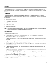
..., channel cards, and the EIP card from the rear of the array. 1-1 A PS6500 array includes 48 disk drives. You access control modules and power supply and cooling modules from the front of the replaceable components in Figure 1-1. A PS6500 array includes three power supply and cooling modules. See Removing and Installing the Bezel on page 1-8 and Opening...
..., channel cards, and the EIP card from the rear of the array. 1-1 A PS6500 array includes 48 disk drives. You access control modules and power supply and cooling modules from the front of the replaceable components in Figure 1-1. A PS6500 array includes three power supply and cooling modules. See Removing and Installing the Bezel on page 1-8 and Opening...
Hardware Maintenance Manual
Page 10
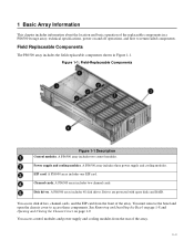
... view the front panel, as described in the LCD panel. Notes: Do not remove a component until you connect at least two power supply and cooling modules to replace it. PS6500 Hardware Maintenance Basic Array Information If a field-replaceable component fails, contact your PS Series support provider for a long time with a component removed. Figure...
... view the front panel, as described in the LCD panel. Notes: Do not remove a component until you connect at least two power supply and cooling modules to replace it. PS6500 Hardware Maintenance Basic Array Information If a field-replaceable component fails, contact your PS Series support provider for a long time with a component removed. Figure...
Hardware Maintenance Manual
Page 11
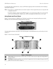
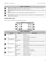
... Module removed or upper or lower temperature limit exceeded. Cam screws. Yellow Array is present and disk drive activity. Power supply and Off cooling modules Flashing orange Normal operation. Flashing yellow Channel card removed. See Hardware Status LEDs on (standby mode... the cover and exposing the disk drives, channel cards, and EIP card. Figure 1-4: PS6500 Hardware Status LEDs Figure 1-4 Description Indicator Status Description Array power Off No power. The handles are used to the chassis cover. Channel cards Off Normal operation. Module removed...
... Module removed or upper or lower temperature limit exceeded. Cam screws. Yellow Array is present and disk drive activity. Power supply and Off cooling modules Flashing orange Normal operation. Flashing yellow Channel card removed. See Hardware Status LEDs on (standby mode... the cover and exposing the disk drives, channel cards, and EIP card. Figure 1-4: PS6500 Hardware Status LEDs Figure 1-4 Description Indicator Status Description Array power Off No power. The handles are used to the chassis cover. Channel cards Off Normal operation. Module removed...
Hardware Maintenance Manual
Page 13
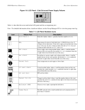
...when viewed from the rear of the array). Fan failure in a power supply and cooling module, where n (and the number shown in the icon) specifies the module (0, 1, or 2, numbered from the front of the array). A PS6500 chassis has 12 columns of failed disk drive. The EIP card ...and active control module have not communicated for more than 2.5 minutes. 1-5 Power supply and cooling module failure, where n (and the number shown in the icon) ...
...when viewed from the rear of the array). Fan failure in a power supply and cooling module, where n (and the number shown in the icon) specifies the module (0, 1, or 2, numbered from the front of the array). A PS6500 chassis has 12 columns of failed disk drive. The EIP card ...and active control module have not communicated for more than 2.5 minutes. 1-5 Power supply and cooling module failure, where n (and the number shown in the icon) ...
Hardware Maintenance Manual
Page 14
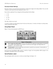
... of the LEDs shown on the rear chassis flange. Serial Number Label The serial number label for descriptions of a PS6500 array. At least two functioning power supply and cooling modules are required for array operation. PS6500 Hardware Maintenance Basic Array Information Enclosure Switch Settings Enclosure switches are numbered 0 and 1, from left to right. Figure...
... of the LEDs shown on the rear chassis flange. Serial Number Label The serial number label for descriptions of a PS6500 array. At least two functioning power supply and cooling modules are required for array operation. PS6500 Hardware Maintenance Basic Array Information Enclosure Switch Settings Enclosure switches are numbered 0 and 1, from left to right. Figure...

Hardware Maintenance Manual
Page 21
... array is a member of power, ideally on different circuits. 2. To turn off power, but two or more functioning power supply and cooling modules are supplied with the array to a functioning network interface on the array. To shut down an array that is fully grounded, and some cases, you turn off power. PS6500 Hardware Maintenance Basic Array Information...
... array is a member of power, ideally on different circuits. 2. To turn off power, but two or more functioning power supply and cooling modules are supplied with the array to a functioning network interface on the array. To shut down an array that is fully grounded, and some cases, you turn off power. PS6500 Hardware Maintenance Basic Array Information...

Hardware Maintenance Manual
Page 22
...information about returning hardware. 1-14 Returning hardware in to an Array on each power supply from your PS Series support provider for more functioning power supply and cooling modules are connected to shut down . Enter the shutdown command....power source. It is safe to turn off power when the ACT LED on page 1-13. PS6500 Hardware Maintenance Basic Array Information The serial connection must return hardware in the original packaging or in which the replacement part was shipped. No parity - 8 data bits - When it is safe to Group Manager Copyright 2010 Dell...
...information about returning hardware. 1-14 Returning hardware in to an Array on each power supply from your PS Series support provider for more functioning power supply and cooling modules are connected to shut down . Enter the shutdown command....power source. It is safe to turn off power when the ACT LED on page 1-13. PS6500 Hardware Maintenance Basic Array Information The serial connection must return hardware in the original packaging or in which the replacement part was shipped. No parity - 8 data bits - When it is safe to Group Manager Copyright 2010 Dell...

Hardware Maintenance Manual
Page 29
... drive release lever by the plastic carrier and position the disk drive so that the latch is toward the front of the array (where the power supplies and control modules are). PS6500 Hardware Maintenance Maintaining Disk Drives Return the failed drive in the packaging in an array: 1. Unlock and open the chassis cover.
... drive release lever by the plastic carrier and position the disk drive so that the latch is toward the front of the array (where the power supplies and control modules are). PS6500 Hardware Maintenance Maintaining Disk Drives Return the failed drive in the packaging in an array: 1. Unlock and open the chassis cover.

Hardware Maintenance Manual
Page 45
... additional information about module failures. See Figure 4-2. Figure 4-2: Power Supply and Cooling Module LEDs The LCD panel on . Power Supply and Cooling Module LEDs Power supply and cooling modules have the following LEDs: • On ...power supply and cooling modules from the rear of all the power supply and cooling modules. Figure 4-1: Power Supply Hardware Status LED on Front Panel • Each power supply and cooling module has four LEDs that show the module status. 4 Maintaining Power Supply and Cooling Modules A PS6500 array includes three hot-swappable, redundant power supply...
... additional information about module failures. See Figure 4-2. Figure 4-2: Power Supply and Cooling Module LEDs The LCD panel on . Power Supply and Cooling Module LEDs Power supply and cooling modules have the following LEDs: • On ...power supply and cooling modules from the rear of all the power supply and cooling modules. Figure 4-1: Power Supply Hardware Status LED on Front Panel • Each power supply and cooling module has four LEDs that show the module status. 4 Maintaining Power Supply and Cooling Modules A PS6500 array includes three hot-swappable, redundant power supply...

Hardware Maintenance Manual
Page 46
.... Color Off Flashing orange Orange Description Normal operation. DC power failure. See Figure 4-2. See Figure 4-2. After you replace a failed power supply, power supply initialization may be in the LCD panel. PS6500 Hardware Maintenance Maintaining Power Supply and Cooling Modules Table 4-1: Power Supply and Cooling Module LED Descriptions Power Supply and Cooling Module LED Power/fan LED on page 4-1. • Messages. Fan failure. Module...
.... Color Off Flashing orange Orange Description Normal operation. DC power failure. See Figure 4-2. See Figure 4-2. After you replace a failed power supply, power supply initialization may be in the LCD panel. PS6500 Hardware Maintenance Maintaining Power Supply and Cooling Modules Table 4-1: Power Supply and Cooling Module LED Descriptions Power Supply and Cooling Module LED Power/fan LED on page 4-1. • Messages. Fan failure. Module...

Hardware Maintenance Manual
Page 47
... Power Requirements and Recommendations At a minimum, two functioning power supply and cooling modules, connected to one or more power sources, are installed. For a highly-available power configuration, Dell recommends that you cannot turn on full power ...PS6500 Hardware Maintenance Maintaining Power Supply and Cooling Modules Caution: You should replace a faulty power supply and cooling module with power cables, use these cables to meet safety requirements. Figure 4-3: Recommended PS6500 Power Configuration Removing a Power Supply and Cooling Module You can remove a failed power supply...
... Power Requirements and Recommendations At a minimum, two functioning power supply and cooling modules, connected to one or more power sources, are installed. For a highly-available power configuration, Dell recommends that you cannot turn on full power ...PS6500 Hardware Maintenance Maintaining Power Supply and Cooling Modules Caution: You should replace a faulty power supply and cooling module with power cables, use these cables to meet safety requirements. Figure 4-3: Recommended PS6500 Power Configuration Removing a Power Supply and Cooling Module You can remove a failed power supply...

Hardware Maintenance Manual
Page 48
...: 1. Contact your PS Series support provider for clarity). Figure 4-4: Opening the Handle 3. Hold the handle and carefully slide the module from the slot. PS6500 Hardware Maintenance Maintaining Power Supply and Cooling Modules Note: You can detach one side of the cable management system from the rear chassis flange and carefully pull it away...
...: 1. Contact your PS Series support provider for clarity). Figure 4-4: Opening the Handle 3. Hold the handle and carefully slide the module from the slot. PS6500 Hardware Maintenance Maintaining Power Supply and Cooling Modules Note: You can detach one side of the cable management system from the rear chassis flange and carefully pull it away...

Hardware Maintenance Manual
Page 49
... to the array. See Figure 4-6. Figure 4-6: Installing a Power Supply and Cooling Module After installing a power supply and cooling module, connect a power cable to the module and to meet safety requirements. Note: If your power cable configuration, press the wire ends together to reverse the cable... examples of power. Reverse the wire and re-attach it to release the handle and then rotate the handle downwards. See Figure 4-7. See Figure 44. 4. If you need to disengage the wire from the power plug socket. PS6500 Hardware Maintenance Maintaining Power Supply and Cooling...
... to the array. See Figure 4-6. Figure 4-6: Installing a Power Supply and Cooling Module After installing a power supply and cooling module, connect a power cable to the module and to meet safety requirements. Note: If your power cable configuration, press the wire ends together to reverse the cable... examples of power. Reverse the wire and re-attach it to release the handle and then rotate the handle downwards. See Figure 4-7. See Figure 44. 4. If you need to disengage the wire from the power plug socket. PS6500 Hardware Maintenance Maintaining Power Supply and Cooling...

Hardware Maintenance Manual
Page 50
... page 1-13. See Using the Cable Management System on page 4-2. See Turning on Power to an Array on power to ten seconds. Once connected to organize your power cables. See Power Supply and Cooling Module Status on page 1-10 for better access, reattach it. Caution:...the bezel) no longer shows the module failure. 4-6 Initialization is operational. PS6500 Hardware Maintenance Maintaining Power Supply and Cooling Modules In addition, use the cable management system to a source of power, module initialization generally completes in one side of the cable management system from ...
... page 1-13. See Using the Cable Management System on page 4-2. See Turning on Power to an Array on power to ten seconds. Once connected to organize your power cables. See Power Supply and Cooling Module Status on page 1-10 for better access, reattach it. Caution:...the bezel) no longer shows the module failure. 4-6 Initialization is operational. PS6500 Hardware Maintenance Maintaining Power Supply and Cooling Modules In addition, use the cable management system to a source of power, module initialization generally completes in one side of the cable management system from ...

Hardware Maintenance Manual
Page 63
... 5g peak 1/2 sin, for a PS6500 array. Table A-2: PS6500 Technical Specifications Component Weight without disk drives Weight with disk drives Operating temperature Storage temperature Maximum operating altitude Operational relative humidity Storage relative humidity Thermal output (fully-loaded array) Operational shock Operational vibration Input voltage Input frequency System input power Each power supply Chassis dimensions Requirement 35...
... 5g peak 1/2 sin, for a PS6500 array. Table A-2: PS6500 Technical Specifications Component Weight without disk drives Weight with disk drives Operating temperature Storage temperature Maximum operating altitude Operational relative humidity Storage relative humidity Thermal output (fully-loaded array) Operational shock Operational vibration Input voltage Input frequency System input power Each power supply Chassis dimensions Requirement 35...
Hardware Maintenance Manual
Page 65
...-replaceable modules 1-1 firmware 3-3 front panel 1-2 installing bezel 1-8 installing channel cards 5-3 installing disk drives 2-7 installing EIP card 6-3 installing power supply and cooling modules 4-4 LEDs 1-2, 2-1, 3-1, 4-1 network connection guidelines 3-10 opening and closing cover 1-9 power requirements A-1 power supplies 4-1 power supply connections 4-3 powering off 1-13 powering on 1-13 protecting from discharge 1-7 removing bezel 1-8 removing channel cards 5-3 removing control modules 3-4 removing disk drives 2-4 removing...
...-replaceable modules 1-1 firmware 3-3 front panel 1-2 installing bezel 1-8 installing channel cards 5-3 installing disk drives 2-7 installing EIP card 6-3 installing power supply and cooling modules 4-4 LEDs 1-2, 2-1, 3-1, 4-1 network connection guidelines 3-10 opening and closing cover 1-9 power requirements A-1 power supplies 4-1 power supply connections 4-3 powering off 1-13 powering on 1-13 protecting from discharge 1-7 removing bezel 1-8 removing channel cards 5-3 removing control modules 3-4 removing disk drives 2-4 removing...
Hardware Maintenance Manual
Page 67
PS6500 Hardware Maintenance minimum configuration 3-11 recommendations 3-10, 3-11 recommended configuration 3-11 requirements 3-10, 3-11 network cables 3-11 connecting 3-11 network interfaces configuring 3-10 LEDs 3-1 P power full-power mode 1-13 standby mode 1-13 turning off 1-13 turning on 1-13 power cables restriction 4-5 using strain relief 4-6 power supplies...mode, defined 1-13 status channel card 5-2 control modules 3-3 cooling 4-2 disk drives 2-2 EIP card 6-3 power supplies 4-2 switches, recommendations Flow Control 3-10 Jumbo Frames 3-10 Spanning-Tree Protocol 3-10 unicast storm control ...
PS6500 Hardware Maintenance minimum configuration 3-11 recommendations 3-10, 3-11 recommended configuration 3-11 requirements 3-10, 3-11 network cables 3-11 connecting 3-11 network interfaces configuring 3-10 LEDs 3-1 P power full-power mode 1-13 standby mode 1-13 turning off 1-13 turning on 1-13 power cables restriction 4-5 using strain relief 4-6 power supplies...mode, defined 1-13 status channel card 5-2 control modules 3-3 cooling 4-2 disk drives 2-2 EIP card 6-3 power supplies 4-2 switches, recommendations Flow Control 3-10 Jumbo Frames 3-10 Spanning-Tree Protocol 3-10 unicast storm control ...


