Hardware Maintenance Manual
Page 3
... Overview of Dell EqualLogic Products ...iii Related Documentation ...v Technical Support and Customer Service ...v Warranty Information ...vi 1 Basic Array Information ...1-1 Field Replaceable Components...1-1 Array Bezel and Front Panel ...1-2 Hardware Status LEDs ...1-3 LCD Panel Display ...1-4 Enclosure Switch Settings ...1-6 Array Back Panel ...1-6 Serial Number Label ...1-6 Protecting Hardware from Electrostatic Discharge 1-7 Removing and Installing the Bezel ...1-8 Opening and Closing the Chassis Cover ...1-9 Using the Cable Management System ...1-10 Turning on Power to an Array...1-13...
... Overview of Dell EqualLogic Products ...iii Related Documentation ...v Technical Support and Customer Service ...v Warranty Information ...vi 1 Basic Array Information ...1-1 Field Replaceable Components...1-1 Array Bezel and Front Panel ...1-2 Hardware Status LEDs ...1-3 LCD Panel Display ...1-4 Enclosure Switch Settings ...1-6 Array Back Panel ...1-6 Serial Number Label ...1-6 Protecting Hardware from Electrostatic Discharge 1-7 Removing and Installing the Bezel ...1-8 Opening and Closing the Chassis Cover ...1-9 Using the Cable Management System ...1-10 Turning on Power to an Array...1-13...
Hardware Maintenance Manual
Page 5
... Interface Processor (EIP) card status and how to have extensive network or storage system experience. iii Administrators are not required to install and remove an EIP card. • Appendix A, Array Technical Specifications, lists the environmental and physical specifications for the array. We hope you for installing or maintaining PS6500 array hardware. However, it may be useful to configure and manage. Preface This manual describes how to maintain the PS6500 storage array hardware, including disks, channel cards, EIP card, control modules, and power supply and cooling modules...
... Interface Processor (EIP) card status and how to have extensive network or storage system experience. iii Administrators are not required to install and remove an EIP card. • Appendix A, Array Technical Specifications, lists the environmental and physical specifications for the array. We hope you for installing or maintaining PS6500 array hardware. However, it may be useful to configure and manage. Preface This manual describes how to maintain the PS6500 storage array hardware, including disks, channel cards, EIP card, control modules, and power supply and cooling modules...
Hardware Maintenance Manual
Page 6
... array, PS Series firmware software allows you to use physical media to provide point-in the event of Virtual Center folders, datastores, and virtual machines. Multipath I/O Device Specific Module (MPIO DSM): Includes a connection awareness-module that understands PS Series network load balancing and facilitates host connections to PS Series groups, and configures and manages multipathing. - Current Customers Please Note: You may not be running the latest versions of data...
... array, PS Series firmware software allows you to use physical media to provide point-in the event of Virtual Center folders, datastores, and virtual machines. Multipath I/O Device Specific Module (MPIO DSM): Includes a connection awareness-module that understands PS Series network load balancing and facilitates host connections to PS Series groups, and configures and manages multipathing. - Current Customers Please Note: You may not be running the latest versions of data...
Hardware Maintenance Manual
Page 9
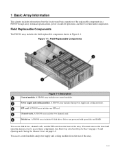
... disks and RAID. You must remove the bezel and open the chassis cover to return failed components. A PS6500 array includes two control modules. A PS6500 array includes one EIP card. A PS6500 array includes 48 disk drives. EIP card. A PS6500 array includes two channel cards. You access disk drives, channel cards, and the EIP card from the rear of the array. See Removing and Installing the Bezel on page 1-8 and Opening and Closing the Chassis Cover on and off operations, and how to access these components. Figure 1-1: Field-Replaceable...
... disks and RAID. You must remove the bezel and open the chassis cover to return failed components. A PS6500 array includes two control modules. A PS6500 array includes one EIP card. A PS6500 array includes 48 disk drives. EIP card. A PS6500 array includes two channel cards. You access disk drives, channel cards, and the EIP card from the rear of the array. See Removing and Installing the Bezel on page 1-8 and Opening and Closing the Chassis Cover on and off operations, and how to access these components. Figure 1-1: Field-Replaceable...
Hardware Maintenance Manual
Page 11
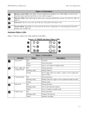
... Power supply failure, fan failure, or upper or lower temperature limit exceeded. Yellow Array is not turned on (standby mode). Yellow Channel card failure. 1-3 These LEDs indicate when hardware problems occur. See Hardware Status LEDs on page 2-1. Figure 1-4: PS6500 Hardware Status LEDs Figure 1-4 Description Indicator Status Description Array power Off No power. Module removed. Channel cards Off Normal operation. The two cam screws secure the array front panel to pull out the chassis, opening the cover and exposing the disk drives, channel cards, and EIP card...
... Power supply failure, fan failure, or upper or lower temperature limit exceeded. Yellow Array is not turned on (standby mode). Yellow Channel card failure. 1-3 These LEDs indicate when hardware problems occur. See Hardware Status LEDs on page 2-1. Figure 1-4: PS6500 Hardware Status LEDs Figure 1-4 Description Indicator Status Description Array power Off No power. Module removed. Channel cards Off Normal operation. The two cam screws secure the array front panel to pull out the chassis, opening the cover and exposing the disk drives, channel cards, and EIP card...

Hardware Maintenance Manual
Page 12
... Panel - Flashing yellow EIP card removed. If the array is a member of the failed drive in the LCD panel. Fan Failure If a disk drive fails, you will also see an icon showing the location of a group and there are no failures, the member name appears in the LCD panel. See Figure 1-8. 1-4 PS6500 Hardware Maintenance Basic Array Information Indicator EIP card Figure 1-4 Description (Continued) Status Description Off Normal operation. LCD Panel Display The LCD panel, located on the array...
... Panel - Flashing yellow EIP card removed. If the array is a member of the failed drive in the LCD panel. Fan Failure If a disk drive fails, you will also see an icon showing the location of a group and there are no failures, the member name appears in the LCD panel. See Figure 1-8. 1-4 PS6500 Hardware Maintenance Basic Array Information Indicator EIP card Figure 1-4 Description (Continued) Status Description Off Normal operation. LCD Panel Display The LCD panel, located on the array...

Hardware Maintenance Manual
Page 21
... power. PS6500 Hardware Maintenance Basic Array Information Turning on Power to an Array There are not supplied with power, and the array is not operational. • Full-power mode. To turn off power in Removing and Installing the Bezel on the array. However, disks and control modules are two power modes for a PS6500 array: • Standby mode. When the array restart completes, if the array is a member of the following procedures: • Use telnet or SSH to connect to an IP address...
... power. PS6500 Hardware Maintenance Basic Array Information Turning on Power to an Array There are not supplied with power, and the array is not operational. • Full-power mode. To turn off power in Removing and Installing the Bezel on the array. However, disks and control modules are two power modes for a PS6500 array: • Standby mode. When the array restart completes, if the array is a member of the following procedures: • Use telnet or SSH to connect to an IP address...
Hardware Maintenance Manual
Page 25
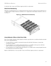
... of disk drives, disk drives 4 to 7 comprise the second column of the array, going front to 47, starting from a backup. Performance may be lost and must be impaired. • If a spare disk drive is not available and the failed disk drive is in a RAID set with no previous disk drive failure, the RAID set that is available, it automatically replaces the failed disk. PS6500 Hardware Maintenance Maintaining Disk Drives If a disk drive fails, contact your PS Series support provider for a replacement...
... of disk drives, disk drives 4 to 7 comprise the second column of the array, going front to 47, starting from a backup. Performance may be lost and must be impaired. • If a spare disk drive is not available and the failed disk drive is in a RAID set with no previous disk drive failure, the RAID set that is available, it automatically replaces the failed disk. PS6500 Hardware Maintenance Maintaining Disk Drives If a disk drive fails, contact your PS Series support provider for a replacement...
Hardware Maintenance Manual
Page 26
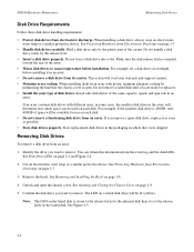
... the chassis cover is to room temperature before installing it as soon as possible. • Store disk drives properly. Store replacement disk drives in the packaging in an array. You can be used on the failed disk. See Disk Drive LEDs on page 1-7. 3. See Protecting Hardware from an array. For example, if the smallest disk drive is closer to the release latch for use on a failed disk drive will void your warranty and support contract...
... the chassis cover is to room temperature before installing it as soon as possible. • Store disk drives properly. Store replacement disk drives in the packaging in an array. You can be used on the failed disk. See Disk Drive LEDs on page 1-7. 3. See Protecting Hardware from an array. For example, if the smallest disk drive is closer to the release latch for use on a failed disk drive will void your warranty and support contract...

Hardware Maintenance Manual
Page 34
...the control modules. Control module failure. In addition, on Front Panel Color Off Flashing orange Orange 3-2 Table 3-3: Control Module Hardware Status LED States Description Normal operation. Cache is starting up or error condition. Active control module (serving network I/O). Array is synchronized with active control module, or error condition. ERR LED Off Green No power. Connected to network. PWR LED Ethernet Port LEDs Left side of each port. PS6500 Hardware Maintenance Maintaining Control Modules • Each Ethernet port has two LEDs that show the network interface...
...the control modules. Control module failure. In addition, on Front Panel Color Off Flashing orange Orange 3-2 Table 3-3: Control Module Hardware Status LED States Description Normal operation. Cache is starting up or error condition. Active control module (serving network I/O). Array is synchronized with active control module, or error condition. ERR LED Off Green No power. Connected to network. PWR LED Ethernet Port LEDs Left side of each port. PS6500 Hardware Maintenance Maintaining Control Modules • Each Ethernet port has two LEDs that show the network interface...
Hardware Maintenance Manual
Page 35
... disabled, initiators that both control modules fail, the array will be functional. A message on the LCD panel (located behind the bezel), on the active control module. Therefore, you should run the same firmware version; Control module failover is a cable connected to take advantage of network failure protection: • Network connection failover. The active control module can reconnect to the group IP address and be redirected to Ethernet 0 can access an interface. If multiple network interfaces are configured and one network interface fails...
... disabled, initiators that both control modules fail, the array will be functional. A message on the LCD panel (located behind the bezel), on the active control module. Therefore, you should run the same firmware version; Control module failover is a cable connected to take advantage of network failure protection: • Network connection failover. The active control module can reconnect to the group IP address and be redirected to Ethernet 0 can access an interface. If multiple network interfaces are configured and one network interface fails...
Hardware Maintenance Manual
Page 38
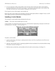
...Control modules are replacing a failed control module, remove the micro SD card from Electrostatic Discharge on page 3-7 and install it in the array, with an empty control module slot. Hold the latches and slide the control module into the slot until you are oriented horizontally in the replacement control module. PS6500 Hardware Maintenance Maintaining Control Modules 4. Installing a Control Module You can install a control module without shutting down the array. See Protecting Hardware from the failed control module as shown in Figure 3-5. Contact your PS Series support...
...Control modules are replacing a failed control module, remove the micro SD card from Electrostatic Discharge on page 3-7 and install it in the array, with an empty control module slot. Hold the latches and slide the control module into the slot until you are oriented horizontally in the replacement control module. PS6500 Hardware Maintenance Maintaining Control Modules 4. Installing a Control Module You can install a control module without shutting down the array. See Protecting Hardware from the failed control module as shown in Figure 3-5. Contact your PS Series support...

Hardware Maintenance Manual
Page 39
... manual for information about cache policies. If a control module fails, remove the microSD card from the slot. This will operate in the replacement control module. Rotate each latch toward the array until the cache battery is fully charged. Replacing the MicroSD Card Each control module includes a microSD card containing the PS Series firmware. If the low-battery-safe cache policy is enabled (the default), the array will make sure that is operational. PS6500 Hardware Maintenance Figure 3-6: Installing a Control Module Maintaining Control Modules...
... manual for information about cache policies. If a control module fails, remove the microSD card from the slot. This will operate in the replacement control module. Rotate each latch toward the array until the cache battery is fully charged. Replacing the MicroSD Card Each control module includes a microSD card containing the PS Series firmware. If the low-battery-safe cache policy is enabled (the default), the array will make sure that is operational. PS6500 Hardware Maintenance Figure 3-6: Installing a Control Module Maintaining Control Modules...

Hardware Maintenance Manual
Page 42
... when using interswitch links. Although an array can use the Group Manager GUI or CLI to assign an IP address and netmask to a switched network and make sure that occur when devices restart, and should enable the port settings (available on switches. After connecting the network interfaces, use Spanning-Tree for a single-cable connection between switches, or trunking for multi-cable connections between hosts and arrays are Gigabit Ethernet. Enable Flow Control on each switch port and NIC...
... when using interswitch links. Although an array can use the Group Manager GUI or CLI to assign an IP address and netmask to a switched network and make sure that occur when devices restart, and should enable the port settings (available on switches. After connecting the network interfaces, use Spanning-Tree for a single-cable connection between switches, or trunking for multi-cable connections between hosts and arrays are Gigabit Ethernet. Enable Flow Control on each switch port and NIC...

Hardware Maintenance Manual
Page 45
... modules connected to a source of all the power supply and cooling modules. Figure 4-2: Power Supply and Cooling Module LEDs The LCD panel on Front Panel • Each power supply and cooling module has four LEDs that show the module status. Figure 4-1: Power Supply Hardware Status LED on the front panel (located behind the bezel) provides additional information about module failures. See Figure 4-2. This LED panel is visible with the bezel on. The power supply and cooling module LEDs are required for array operation. Power Supply and Cooling Module LEDs Power supply...
... modules connected to a source of all the power supply and cooling modules. Figure 4-2: Power Supply and Cooling Module LEDs The LCD panel on Front Panel • Each power supply and cooling module has four LEDs that show the module status. Figure 4-1: Power Supply Hardware Status LED on the front panel (located behind the bezel) provides additional information about module failures. See Figure 4-2. This LED panel is visible with the bezel on. The power supply and cooling module LEDs are required for array operation. Power Supply and Cooling Module LEDs Power supply...

Hardware Maintenance Manual
Page 46
... a Power Supply Fails If one power supply and cooling module fails, the array will shut down automatically. Module removed. No power. Power Supply and Cooling Module Status You can identify a failure on the console, in the event log, or in the Group Manager GUI Alarms panel describes a power supply and cooling module failure. • Group Manager GUI and CLI output. See Figure 1-9. PS6500 Hardware Maintenance Maintaining Power Supply and Cooling Modules Table 4-1: Power Supply and Cooling Module LED Descriptions Power Supply and Cooling Module LED Power/fan LED on array...
... a Power Supply Fails If one power supply and cooling module fails, the array will shut down automatically. Module removed. No power. Power Supply and Cooling Module Status You can identify a failure on the console, in the event log, or in the Group Manager GUI Alarms panel describes a power supply and cooling module failure. • Group Manager GUI and CLI output. See Figure 1-9. PS6500 Hardware Maintenance Maintaining Power Supply and Cooling Modules Table 4-1: Power Supply and Cooling Module LED Descriptions Power Supply and Cooling Module LED Power/fan LED on array...

Hardware Maintenance Manual
Page 52
... Card LEDs on array front panel. If a channel card fails, contact your PS Series support provider for a replacement. Normal condition. Channel Card Status You can identify a channel card failure by: • LEDs. The Member Controllers window or the member select show channelcards command output shows a failure. Note: Do not remove a failed channel card until you are described in the Group Manager GUI Alarms panel describes a channel card failure. • Group Manager GUI and CLI output. PS6500 Hardware Maintenance...
... Card LEDs on array front panel. If a channel card fails, contact your PS Series support provider for a replacement. Normal condition. Channel Card Status You can identify a channel card failure by: • LEDs. The Member Controllers window or the member select show channelcards command output shows a failure. Note: Do not remove a failed channel card until you are described in the Group Manager GUI Alarms panel describes a channel card failure. • Group Manager GUI and CLI output. PS6500 Hardware Maintenance...

Hardware Maintenance Manual
Page 59
... device. Do not remove a failed EIP card until you are ready to operate. A message on the LCD panel (located behind the bezel), on page 1-8. 3. See Opening and Closing the Chassis Cover on page 1-7. • Handle EIP cards carefully. Notes: For proper array cooling, minimize the time that the chassis is yellow. PS6500 Hardware Maintenance Maintaining the EIP Card EIP Card Status You can replace a failed EIP card without affecting array operation. Array Behavior When an EIP Card Fails...
... device. Do not remove a failed EIP card until you are ready to operate. A message on the LCD panel (located behind the bezel), on page 1-8. 3. See Opening and Closing the Chassis Cover on page 1-7. • Handle EIP cards carefully. Notes: For proper array cooling, minimize the time that the chassis is yellow. PS6500 Hardware Maintenance Maintaining the EIP Card EIP Card Status You can replace a failed EIP card without affecting array operation. Array Behavior When an EIP Card Fails...
Hardware Maintenance Manual
Page 65
...panel 1-6 batteries 3-1 bezel description 1-2 installing 1-8 removing 1-8 cable management system 1-10 channel cards 5-1 control module restriction 3-6 control modules 3-1 cooling modules 4-1 cooling requirement 1-2 disk drives 2-1 EIP card 6-1 enclosure switches 1-6 environmental requirements A-1 fans 4-1 field-replaceable modules 1-1 firmware 3-3 front panel 1-2 installing bezel 1-8 installing channel cards 5-3 installing disk drives 2-7 installing EIP card 6-3 installing power supply and cooling modules 4-4 LEDs 1-2, 2-1, 3-1, 4-1 network connection guidelines 3-10 opening and closing cover...
...panel 1-6 batteries 3-1 bezel description 1-2 installing 1-8 removing 1-8 cable management system 1-10 channel cards 5-1 control module restriction 3-6 control modules 3-1 cooling modules 4-1 cooling requirement 1-2 disk drives 2-1 EIP card 6-1 enclosure switches 1-6 environmental requirements A-1 fans 4-1 field-replaceable modules 1-1 firmware 3-3 front panel 1-2 installing bezel 1-8 installing channel cards 5-3 installing disk drives 2-7 installing EIP card 6-3 installing power supply and cooling modules 4-4 LEDs 1-2, 2-1, 3-1, 4-1 network connection guidelines 3-10 opening and closing cover...
Hardware Maintenance Manual
Page 67
... cables 3-11 connecting 3-11 network interfaces configuring 3-10 LEDs 3-1 P power full-power mode 1-13 standby mode 1-13 turning off 1-13 turning on 1-13 power cables restriction 4-5 using strain relief 4-6 power supplies cable strain relief 4-6 connecting array 4-3 indications of failure 4-2 initialization 4-6 installing 4-4 LEDs 4-1 locating modules 4-2 maintaining 4-1 removing module 4-3 requirements 4-2 using UPS systems 4-3 verifying operational status 4-6 R requirements channel cards 5-3 control modules 3-4 cooling 4-1 disk drives 2-4 EIP card 6-3 environmental A-1 firmware 3-3 hardware...
... cables 3-11 connecting 3-11 network interfaces configuring 3-10 LEDs 3-1 P power full-power mode 1-13 standby mode 1-13 turning off 1-13 turning on 1-13 power cables restriction 4-5 using strain relief 4-6 power supplies cable strain relief 4-6 connecting array 4-3 indications of failure 4-2 initialization 4-6 installing 4-4 LEDs 4-1 locating modules 4-2 maintaining 4-1 removing module 4-3 requirements 4-2 using UPS systems 4-3 verifying operational status 4-6 R requirements channel cards 5-3 control modules 3-4 cooling 4-1 disk drives 2-4 EIP card 6-3 environmental A-1 firmware 3-3 hardware...


