
User's Guide
Page 12
... connector Signal cable type Digital: detachable, DVI-D, solid pins, shipped detached from the monitor Digital: DisplayPort, 20pin Analog: attachable, D-Sub, 15 pins, shipped attached to the monitor Digital: detachable, DVI-D, solid pins, shipped detached from the monitor Digital: DisplayPort, 20pin Analog..., Multi-stream transport (MST), 3D stereo transport , HBR Audio (or high data rate audio) Physical Characteristics Model P1913 P1913S P2213 15-pin D-subminiature, blue 15-pin D-subminiature, blue 15-pin D-subminiature, blue Connector type connector; DVI-D, white connector; ...
... connector Signal cable type Digital: detachable, DVI-D, solid pins, shipped detached from the monitor Digital: DisplayPort, 20pin Analog: attachable, D-Sub, 15 pins, shipped attached to the monitor Digital: detachable, DVI-D, solid pins, shipped detached from the monitor Digital: DisplayPort, 20pin Analog..., Multi-stream transport (MST), 3D stereo transport , HBR Audio (or high data rate audio) Physical Characteristics Model P1913 P1913S P2213 15-pin D-subminiature, blue 15-pin D-subminiature, blue 15-pin D-subminiature, blue Connector type connector; DVI-D, white connector; ...
User's Guide
Page 17
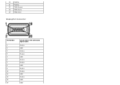
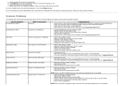
20 Floating 21 Floating 22 TMDS Ground 23 TMDS Clock+ 24 TMDS Clock- DisplayPort Connector Pin Number 1 2 3 4 5 6 7 8 9 10 11 12 13 14 20-pin Side of the Connected Signal Cable ML0(p) GND ML0(n) ML1(p) GND ML1(n) ML2(p) GND ML2(n) ML3(p) GND ML3(n) GND GND
20 Floating 21 Floating 22 TMDS Ground 23 TMDS Clock+ 24 TMDS Clock- DisplayPort Connector Pin Number 1 2 3 4 5 6 7 8 9 10 11 12 13 14 20-pin Side of the Connected Signal Cable ML0(p) GND ML0(n) ML1(p) GND ML1(n) ML2(p) GND ML2(n) ML3(p) GND ML3(n) GND GND
User's Guide
Page 22
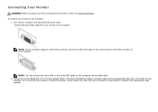
... procedures in this section, follow the Safety Instructions. Connect the white (digital DVI-D) or the blue (analog VGA) or the black (DisplayPort) display connector cable to the computer: 1. Use all cables only when they are connected to the computer at the same time. 2. Connecting Your Monitor WARNING: Before you begin any of your...
... procedures in this section, follow the Safety Instructions. Connect the white (digital DVI-D) or the blue (analog VGA) or the black (DisplayPort) display connector cable to the computer: 1. Use all cables only when they are connected to the computer at the same time. 2. Connecting Your Monitor WARNING: Before you begin any of your...
User's Guide
Page 23
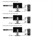
Connecting the white DVI cable Connecting the blue VGA cable Connecting the black DisplayPort cable
Connecting the white DVI cable Connecting the blue VGA cable Connecting the black DisplayPort cable
User's Guide
Page 36
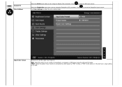
Press Use Color Settings to select the DisplayPort input source. Input Color Format Allows you to set the video input mode to: RGB: Select this option if your monitor is connected to a computer or DVD player using the VGA and DVI cable. to adjust the color setting mode. ... setting is connected to a DVD player by YPbPr to VGA, or YPbPr to select the DVI input source. Select the DisplayPort input when you are using the DisplayPort (DP) connector. Press to DVI cable; DisplayPort Color Settings Select the DVI-D input when you are using the Digital (DVI) connector.
Press Use Color Settings to select the DisplayPort input source. Input Color Format Allows you to set the video input mode to: RGB: Select this option if your monitor is connected to a computer or DVD player using the VGA and DVI cable. to adjust the color setting mode. ... setting is connected to a DVD player by YPbPr to VGA, or YPbPr to select the DVI input source. Select the DisplayPort input when you are using the DisplayPort (DP) connector. Press to DVI cable; DisplayPort Color Settings Select the DVI-D input when you are using the Digital (DVI) connector.
User's Guide
Page 53
... the Input Source Select button. Relocate the monitor and test in diagnostics. To exit, press Button 4 again. Eliminate video extension cables. For more information on the front panel again. Auto Adjust via OSD. 4. Ensure that can occur in self-test mode. ...Check environmental factors. Press Button 4 on Dell Monitor Quality and Pixel Policy, see Dell Support site at : support.dell.com. Repeat steps 5 and 6 to Factory Settings. For more information on -off . NOTE: When using DVI-D/DisplayPort input, the positioning adjustments are also in LCD ...
... the Input Source Select button. Relocate the monitor and test in diagnostics. To exit, press Button 4 again. Eliminate video extension cables. For more information on the front panel again. Auto Adjust via OSD. 4. Ensure that can occur in self-test mode. ...Check environmental factors. Press Button 4 on Dell Monitor Quality and Pixel Policy, see Dell Support site at : support.dell.com. Repeat steps 5 and 6 to Factory Settings. For more information on -off . NOTE: When using DVI-D/DisplayPort input, the positioning adjustments are also in LCD ...


