
Dell OptiPlex XE2 Series Setup And Features Information
Page 1
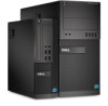
... Regulatory Model: D13M, D07S Regulatory Type: D13M001, D07S001 2013 - 03 power-supply diagnostic light 11. Front and Back View Figure 1. power-supply diagnostic button 12. power connector 13. back panel connectors 14. Front and Back View Of Mini-Tower 1. security-cable slot 16. Dell OptiPlex XE2 Setup And Features Information About Warnings WARNING: A WARNING indicates a potential...
... Regulatory Model: D13M, D07S Regulatory Type: D13M001, D07S001 2013 - 03 power-supply diagnostic light 11. Front and Back View Figure 1. power-supply diagnostic button 12. power connector 13. back panel connectors 14. Front and Back View Of Mini-Tower 1. security-cable slot 16. Dell OptiPlex XE2 Setup And Features Information About Warnings WARNING: A WARNING indicates a potential...

Dell OptiPlex XE2 Series Setup And Features Information
Page 3
...: Before you did not order them. 1. optical drive 2. drive activity light 9. network link integrity light 5. DisplayPort connectors (2) 10. VGA Adapter 3 power button, power light 4. For additional best practices information, see www.dell.com/regulatory_compliance NOTE: Some devices may not be included if you begin any of the following cables: Figure 5. 1. Back Panel View...
...: Before you did not order them. 1. optical drive 2. drive activity light 9. network link integrity light 5. DisplayPort connectors (2) 10. VGA Adapter 3 power button, power light 4. For additional best practices information, see www.dell.com/regulatory_compliance NOTE: Some devices may not be included if you begin any of the following cables: Figure 5. 1. Back Panel View...

Dell OptiPlex XE2 Series Setup And Features Information
Page 4
USB Connection 3. Network Connection 4. Figure 10. Connect the USB keyboard or mouse (optional). Connect the network cable (optional). Figure 6. Connect the power cable(s). Figure 8. Figure 9. Press the power buttons on the monitor and the computer. 4 DisplayPort Cable Figure 7. Connecting Power 5. VGA To DisplayPort Adapter 2.
USB Connection 3. Network Connection 4. Figure 10. Connect the USB keyboard or mouse (optional). Connect the network cable (optional). Figure 6. Connect the power cable(s). Figure 8. Figure 9. Press the power buttons on the monitor and the computer. 4 DisplayPort Cable Figure 7. Connecting Power 5. VGA To DisplayPort Adapter 2.
Dell OptiPlex XE2 Series Setup And Features Information
Page 5
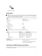
... compliance with the requirements of your computer, click Start → Help and Support and select the option to ship with your computer. Power: Voltage Coin-cell battery Wattage: Mini-Tower Small Form Factor Maximum heat dissipation: Mini-Tower Small Form Factor 100 VAC to 65W or...only those required by region. Figure 11. For more information regarding the configuration of the official Mexican standards (NOM). 5 Turning On Power Specifications NOTE: Offerings may vary by law to view information about your computer. The following information is calculated by using the...
... compliance with the requirements of your computer, click Start → Help and Support and select the option to ship with your computer. Power: Voltage Coin-cell battery Wattage: Mini-Tower Small Form Factor Maximum heat dissipation: Mini-Tower Small Form Factor 100 VAC to 65W or...only those required by region. Figure 11. For more information regarding the configuration of the official Mexican standards (NOM). 5 Turning On Power Specifications NOTE: Offerings may vary by law to view information about your computer. The following information is calculated by using the...

Owner's Manual - Mini Tower
Page 3
... Hard Drive...16 Removing the Optical Drive...16 Installing the Optical Drive...17 Removing the Speaker...17 Installing the Speaker...18 Removing the Power Supply...18 Installing the Power Supply...20 Removing the Heat-Sink Assembly...20 Installing the Heat Sink Assembly...20 Removing the Processor...20 Installing the Processor...21 Removing...
... Hard Drive...16 Removing the Optical Drive...16 Installing the Optical Drive...17 Removing the Speaker...17 Installing the Speaker...18 Removing the Power Supply...18 Installing the Power Supply...20 Removing the Heat-Sink Assembly...20 Installing the Heat Sink Assembly...20 Removing the Processor...20 Installing the Processor...21 Removing...

Owner's Manual - Mini Tower
Page 4
Installing the System Fan...22 Removing the Thermal Sensor...22 Installing the Thermal Sensor...24 Removing the Power Switch...24 Installing the Power Switch...25 Removing the Input/Output (I/O) Panel...26 Installing the Input/Output (I/O) Panel...27 Removing the System Board...27 Installing the System Board...28 System... System and/or Setup Password 42 Disabling a System Password...42 4 Diagnostics...45 Enhanced Pre-Boot System Assessment (ePSA) Diagnostics 45 5 Troubleshooting Your Computer 47 Power LED Diagnostics...47 Beep Code...48 Error Messages...48 6 Specifications...53 7 Contacting...
Installing the System Fan...22 Removing the Thermal Sensor...22 Installing the Thermal Sensor...24 Removing the Power Switch...24 Installing the Power Switch...25 Removing the Input/Output (I/O) Panel...26 Installing the Input/Output (I/O) Panel...27 Removing the System Board...27 Installing the System Board...28 System... System and/or Setup Password 42 Disabling a System Password...42 4 Diagnostics...45 Enhanced Pre-Boot System Assessment (ePSA) Diagnostics 45 5 Troubleshooting Your Computer 47 Power LED Diagnostics...47 Beep Code...48 Error Messages...48 6 Specifications...53 7 Contacting...

Owner's Manual - Mini Tower
Page 5
...only be replaced or--if purchased separately--installed by your warranty. Turn off your computer (see the Regulatory Compliance Homepage at www.dell.com/ regulatory_compliance CAUTION: Many repairs may appear differently than shown in this type of the computer. Disconnect your computer and all network... touching an unpainted metal surface, such as a processor by its edges, not by its metal mounting bracket. Press and hold the power button while the computer is flat and clean to prevent the computer cover from being scratched. 2. You should only perform troubleshooting and ...
...only be replaced or--if purchased separately--installed by your warranty. Turn off your computer (see the Regulatory Compliance Homepage at www.dell.com/ regulatory_compliance CAUTION: Many repairs may appear differently than shown in this type of the computer. Disconnect your computer and all network... touching an unpainted metal surface, such as a processor by its edges, not by its metal mounting bracket. Press and hold the power button while the computer is flat and clean to prevent the computer cover from being scratched. 2. You should only perform troubleshooting and ...

Owner's Manual - Mini Tower
Page 6
...losing data, save and close all open files and exit all open programs before turning on your computer, ground yourself by running the Dell Diagnostics. 6 Swipe in the lower-right corner of the Start menu as the metal at the back of the computer. b. Point ...touching anything inside your computer. 5. Click Start . 2. Shut down a. In Windows 7: and select Shut down your operating system, press and hold the power button for about 6 seconds to their electrical outlets. 4. Click Start . 2. Click the arrow in from the right edge of the screen and click Settings...
...losing data, save and close all open files and exit all open programs before turning on your computer, ground yourself by running the Dell Diagnostics. 6 Swipe in the lower-right corner of the Start menu as the metal at the back of the computer. b. Point ...touching anything inside your computer. 5. Click Start . 2. Shut down a. In Windows 7: and select Shut down your operating system, press and hold the power button for about 6 seconds to their electrical outlets. 4. Click Start . 2. Click the arrow in from the right edge of the screen and click Settings...

Owner's Manual - Mini Tower
Page 11
Disconnect the power cable from the computer. 11 NOTE: If your computer has a powered expansion card perform step 3 and step 4, else move to step 5. 3. Rotate the release tab on the card-retention latch upward. 4. Ease the card up from its connector and remove it from the card.
Disconnect the power cable from the computer. 11 NOTE: If your computer has a powered expansion card perform step 3 and step 4, else move to step 5. 3. Rotate the release tab on the card-retention latch upward. 4. Ease the card up from its connector and remove it from the card.

Owner's Manual - Mini Tower
Page 13
...on the card-retention latch downward. 4. NOTE: If your computer may be installed in After Working Inside Your Computer. Connect the power cable from the card. 3. But, all populated channels must have identical configurations. • Memory modules must be labeled differently depending... when configuring your system memory: • Memory modules of the slowest installed memory modules. Follow the procedures in your computer has a powered expansion card perform step 2, else move to step 3. 2. Install the cover. 5. Installing the Expansion Card 1. NOTE: The memory ...
...on the card-retention latch downward. 4. NOTE: If your computer may be installed in After Working Inside Your Computer. Connect the power cable from the card. 3. But, all populated channels must have identical configurations. • Memory modules must be labeled differently depending... when configuring your system memory: • Memory modules of the slowest installed memory modules. Follow the procedures in your computer has a powered expansion card perform step 2, else move to step 3. 2. Install the cover. 5. Installing the Expansion Card 1. NOTE: The memory ...

Owner's Manual - Mini Tower
Page 15
...-Cell Battery 1. Install the expansion card. 3. Follow the procedures in After Working Inside Your Computer. Remove: a) cover b) front bezel 3. Disconnect the data cable and the power cable from the hard-drive bracket. 15 Install the cover. 4. Follow the procedures in Before Working Inside Your Computer. 2. Place the coin cell battery in...
...-Cell Battery 1. Install the expansion card. 3. Follow the procedures in After Working Inside Your Computer. Remove: a) cover b) front bezel 3. Disconnect the data cable and the power cable from the hard-drive bracket. 15 Install the cover. 4. Follow the procedures in Before Working Inside Your Computer. 2. Place the coin cell battery in...

Owner's Manual - Mini Tower
Page 16
... brackets inward and slide the hard-drive bracket into the hard-drive bracket. 2. Remove: a) cover b) front bezel 3. Disconnect the data cable and the power cable from the back of the computer. 16 5. Insert the hard drive into the bay. 3. Follow the procedures in Before Working Inside Your Computer. 2.... Removing the Optical Drive 1. Repeat the steps 3 to the back of the hard-drive. 4. Connect the data cable and the power cable to 5 for the second hard drive, if available. Installing the Hard Drive 1. Slide down and hold the optical-drive latch to unlock the ...
... brackets inward and slide the hard-drive bracket into the hard-drive bracket. 2. Remove: a) cover b) front bezel 3. Disconnect the data cable and the power cable from the back of the computer. 16 5. Insert the hard drive into the bay. 3. Follow the procedures in Before Working Inside Your Computer. 2.... Removing the Optical Drive 1. Repeat the steps 3 to the back of the hard-drive. 4. Connect the data cable and the power cable to 5 for the second hard drive, if available. Installing the Hard Drive 1. Slide down and hold the optical-drive latch to unlock the ...

Owner's Manual - Mini Tower
Page 17
... cover. 3. Press down the speaker-securing tab and slide the speaker upwards to remove the second optical drive (if available). Connect the data cable and power cable to the back of the computer till it is secured by the optical-drive latch. 2. Follow the procedures in After Working Inside Your Computer...
... cover. 3. Press down the speaker-securing tab and slide the speaker upwards to remove the second optical drive (if available). Connect the data cable and power cable to the back of the computer till it is secured by the optical-drive latch. 2. Follow the procedures in After Working Inside Your Computer...

Owner's Manual - Mini Tower
Page 18
Slide the speaker downwards into the chassis clip and connect the speaker cable to secure it. 2. Thread the speaker cable into its slot to the system board. 3. Follow the procedures in power cables from the system board and release the cable from the tab. 18 Installing the Speaker 1. Remove the cover. 3. Disconnect the 4-pin and 8-in Before Working Inside Your Computer. 2. Follow the procedures in After Working Inside Your Computer. Removing the Power Supply 1. Install the cover. 4.
Slide the speaker downwards into the chassis clip and connect the speaker cable to secure it. 2. Thread the speaker cable into its slot to the system board. 3. Follow the procedures in power cables from the system board and release the cable from the tab. 18 Installing the Speaker 1. Remove the cover. 3. Disconnect the 4-pin and 8-in Before Working Inside Your Computer. 2. Follow the procedures in After Working Inside Your Computer. Removing the Power Supply 1. Install the cover. 4.

Owner's Manual - Mini Tower
Page 19
Remove the screws that secure the power supply to the back of the computer. 19 4. Lift and remove the power supply out of the computer. 5. Push in on the blue release tab beside the power supply, and slide the power supply towards the front of the computer.
Remove the screws that secure the power supply to the back of the computer. 19 4. Lift and remove the power supply out of the computer. 5. Push in on the blue release tab beside the power supply, and slide the power supply towards the front of the computer.

Owner's Manual - Mini Tower
Page 20
... order to secure the heat sink assembly to the computer. 3. Install the cover. 5. Removing the Processor 1. Connect the 4-pin and 8-pin power cables to the system board. 4. Removing the Heat-Sink Assembly 1. Tighten the captive screws in an antistatic bag. 20 Follow the procedures in ...Before Working Inside Your Computer. 2. Tighten the screws to secure the power supply to the back of the system to release it . 2. Remove: a) cover b) heat-sink assembly 3. Disconnect the fan cable from the...
... order to secure the heat sink assembly to the computer. 3. Install the cover. 5. Removing the Processor 1. Connect the 4-pin and 8-pin power cables to the system board. 4. Removing the Heat-Sink Assembly 1. Tighten the captive screws in an antistatic bag. 20 Follow the procedures in ...Before Working Inside Your Computer. 2. Tighten the screws to secure the power supply to the back of the system to release it . 2. Remove: a) cover b) heat-sink assembly 3. Disconnect the fan cable from the...

Owner's Manual - Mini Tower
Page 24
Remove the: a) cover b) front bezel c) optical drive 3. Install the cover. 5. Release the power-switch cable from the system board. 4. Installing the Thermal Sensor 1. Removing the Power Switch 1. Thread the thermal-sensor cable into the chassis clips. 3. Follow the procedures in Before Working Inside Your Computer. 2. Disconnect the power-switch cable from the chassis clips. 24 Connect the thermal-sensor cable to the chassis. 2. Follow the procedures in After Working Inside Your Computer. Secure the thermal sensor to the system board. 4.
Remove the: a) cover b) front bezel c) optical drive 3. Install the cover. 5. Release the power-switch cable from the system board. 4. Installing the Thermal Sensor 1. Removing the Power Switch 1. Thread the thermal-sensor cable into the chassis clips. 3. Follow the procedures in Before Working Inside Your Computer. 2. Disconnect the power-switch cable from the chassis clips. 24 Connect the thermal-sensor cable to the chassis. 2. Follow the procedures in After Working Inside Your Computer. Secure the thermal sensor to the system board. 4.

Owner's Manual - Mini Tower
Page 25
Thread the power-switch cable into the chassis clips. 4. Connect the power-switch cable to the chassis. 3. Press the clips on both side of the computer. 2. Installing the Power Switch 1. Follow the procedures in through the front of the power switch to release it from the chassis and, slide to remove the power switch along its cable from the computer. Slide the power switch in After Working Inside Your Computer. 25 Install the: a) optical drive b) front bezel c) cover 6. 5. Secure the power-switch cable to the system board. 5.
Thread the power-switch cable into the chassis clips. 4. Connect the power-switch cable to the chassis. 3. Press the clips on both side of the computer. 2. Installing the Power Switch 1. Follow the procedures in through the front of the power switch to release it from the chassis and, slide to remove the power switch along its cable from the computer. Slide the power switch in After Working Inside Your Computer. 25 Install the: a) optical drive b) front bezel c) cover 6. 5. Secure the power-switch cable to the system board. 5.

Owner's Manual - Mini Tower
Page 29
...x1 slot 4. speaker connector 29 PCI Express x16 slot (wired as x4) 2. intrusion switch connector 7. 4-pin CPU power connecter 8. internal USB 2.0 connector 21. coin-cell battery 5. front power-switch connector 13. 8-pin power connector 14. front panel USB connector 18. password reset jumper 20. RTCRST jumper connector 22. PCI slot 3. DDR DIMM... 1. heat-sink fan connector 11. CPU Socket 10. system fan connector 9. SATA connectors 15. System Board Components Figure 1. HDD and optical drive power connector 16. PCI Express x16 slot 6. SATA connectors 17.
...x1 slot 4. speaker connector 29 PCI Express x16 slot (wired as x4) 2. intrusion switch connector 7. 4-pin CPU power connecter 8. internal USB 2.0 connector 21. coin-cell battery 5. front power-switch connector 13. 8-pin power connector 14. front panel USB connector 18. password reset jumper 20. RTCRST jumper connector 22. PCI slot 3. DDR DIMM... 1. heat-sink fan connector 11. CPU Socket 10. system fan connector 9. SATA connectors 15. System Board Components Figure 1. HDD and optical drive power connector 16. PCI Express x16 slot 6. SATA connectors 17.

Owner's Manual - Mini Tower
Page 31
During the Power-on Self Test (POST), when the Dell logo appears, you can: • Access System Setup by pressing key • Bring up the one-time boot menu by pressing key The one-time ... the NVRAM settings after you add or remove hardware • View the system hardware configuration • Enable or disable integrated devices • Set performance and power management thresholds • Manage your computer hardware and specify BIOS‐level options. 3 System Setup System Setup enables you to manage your computer security Boot...
During the Power-on Self Test (POST), when the Dell logo appears, you can: • Access System Setup by pressing key • Bring up the one-time boot menu by pressing key The one-time ... the NVRAM settings after you add or remove hardware • View the system hardware configuration • Enable or disable integrated devices • Set performance and power management thresholds • Manage your computer hardware and specify BIOS‐level options. 3 System Setup System Setup enables you to manage your computer security Boot...


