Service Manual
Page 12
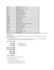
... carefully fit it down over the pins. System Board Jumpers Jumpers are small blocks on the system board. 2 Line-out connector 3 Microphone connector 4 NIC connector 5 Video connector 6 Serial port 2 connector 7 USB connectors (2) 8 Keyboard (lower) and mouse (upper) connectors 9 Parallel port (upper) and serial port 1 (lower) connectors 10 Microprocessor connector 11 RIMM...
... carefully fit it down over the pins. System Board Jumpers Jumpers are small blocks on the system board. 2 Line-out connector 3 Microphone connector 4 NIC connector 5 Video connector 6 Serial port 2 connector 7 USB connectors (2) 8 Keyboard (lower) and mouse (upper) connectors 9 Parallel port (upper) and serial port 1 (lower) connectors 10 Microprocessor connector 11 RIMM...
Service Manual
Page 13
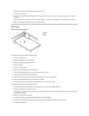
... Microprocessor fan connector Hard-disk drive LED connector EIDE interface connector Chassis intrusion switch connector Keyboard connector Modem audio connector Video connector Mouse connector Control panel connector Parallel port connector; Reserved (do not change ). Real-time clock reset. Expansion... input connector 3.3-V power input connector Riser board connector Serial port connector Primary microprocessor connector USB connectors Expansion Cards Each GX200 low-profile chassis can accommodate 32-bit PCI expansion cards and 16-bit and 8-bit ISA expansion cards, depending ...
... Microprocessor fan connector Hard-disk drive LED connector EIDE interface connector Chassis intrusion switch connector Keyboard connector Modem audio connector Video connector Mouse connector Control panel connector Parallel port connector; Reserved (do not change ). Real-time clock reset. Expansion... input connector 3.3-V power input connector Riser board connector Serial port connector Primary microprocessor connector USB connectors Expansion Cards Each GX200 low-profile chassis can accommodate 32-bit PCI expansion cards and 16-bit and 8-bit ISA expansion cards, depending ...
Service Manual
Page 28
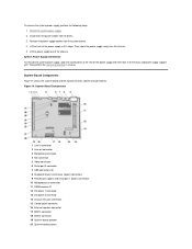
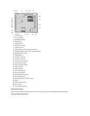
... in reverse. Figure 14. Remove the power supply cables from the chassis. 5. System Board Components 1 Line-in connector 2 Line-out connector 3 Microphone connector 4 NIC connector 5 Video connector 6 Serial port 2 connector 7 USB connectors (2) 8 Keyboard (lower) and mouse (upper) connectors 9 Parallel port (upper) and serial port 1 (lower) connectors 10 Microprocessor connector 11 RIMM...
... in reverse. Figure 14. Remove the power supply cables from the chassis. 5. System Board Components 1 Line-in connector 2 Line-out connector 3 Microphone connector 4 NIC connector 5 Video connector 6 Serial port 2 connector 7 USB connectors (2) 8 Keyboard (lower) and mouse (upper) connectors 9 Parallel port (upper) and serial port 1 (lower) connectors 10 Microprocessor connector 11 RIMM...
Service Manual
Page 30
... NIC connector External speaker connector Microprocessor fan connector Hard-disk drive LED connector EIDE interface connector Chassis intrusion switch connector Keyboard connector Modem audio connector Video connector Mouse connector Control panel connector Parallel port connector;
... NIC connector External speaker connector Microprocessor fan connector Hard-disk drive LED connector EIDE interface connector Chassis intrusion switch connector Keyboard connector Modem audio connector Video connector Mouse connector Control panel connector Parallel port connector;
Service Manual
Page 36
... board, perform the following steps: 1. Disconnect all externally accessible drives and brackets partially out of the way. 4. Remove the AGP card brace and the AGP video card. 7. Slide the system board toward the front of the chassis (see Figure 28). 10. Rotate the system power supply out of the chassis. 8. Set...
... board, perform the following steps: 1. Disconnect all externally accessible drives and brackets partially out of the way. 4. Remove the AGP card brace and the AGP video card. 7. Slide the system board toward the front of the chassis (see Figure 28). 10. Rotate the system power supply out of the chassis. 8. Set...
Service Manual
Page 52
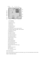
System Board Jumpers Figure 25. 1 Line-in connector 2 Line-out connector 3 Microphone connector 4 NIC connector 5 Video connector 6 Serial port 2 connector 7 USB connectors (2) 8 Keyboard (lower) and mouse (upper) connectors 9 Parallel port (upper) and serial port 1 (lower) connectors 10 Microprocessor connector 11 RIMM ...
System Board Jumpers Figure 25. 1 Line-in connector 2 Line-out connector 3 Microphone connector 4 NIC connector 5 Video connector 6 Serial port 2 connector 7 USB connectors (2) 8 Keyboard (lower) and mouse (upper) connectors 9 Parallel port (upper) and serial port 1 (lower) connectors 10 Microprocessor connector 11 RIMM ...
Service Manual
Page 54
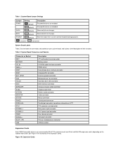
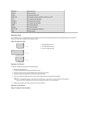
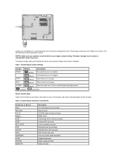
...PCI expansion-card connector Main power input connector 3.3-V power input connector Riser board connector Serial port connector Primary microprocessor connector USB connectors Expansion Cards Each GX200 chassis can accommodate 32-bit PCI expansion cards and 16-bit and 8-bit ISA expansion cards, depending on the installed riser board. See Figure ...26 for examples of its connector. 5. Figure 26. MONITOR MOUSE PANEL PARALLEL PCIn* POWER_1 POWER_2 RISER SERIALn SLOT1_PRI USB Video connector Mouse connector Control panel connector Parallel port connector;
...PCI expansion-card connector Main power input connector 3.3-V power input connector Riser board connector Serial port connector Primary microprocessor connector USB connectors Expansion Cards Each GX200 chassis can accommodate 32-bit PCI expansion cards and 16-bit and 8-bit ISA expansion cards, depending on the installed riser board. See Figure ...26 for examples of its connector. 5. Figure 26. MONITOR MOUSE PANEL PARALLEL PCIn* POWER_1 POWER_2 RISER SERIALn SLOT1_PRI USB Video connector Mouse connector Control panel connector Parallel port connector;
Service Manual
Page 72
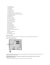
System Board Jumpers Table 1 lists the system board jumpers and their settings. 1 Line-in connector 2 Line-out connector 3 Microphone connector 4 NIC connector 5 Video connector 6 Serial port 2 connector 7 USB connectors (2) 8 Keyboard (lower) and mouse (upper) connectors 9 Parallel port (upper) and serial port 1 (lower) connectors 10 Microprocessor connector 11 RIMM ...
System Board Jumpers Table 1 lists the system board jumpers and their settings. 1 Line-in connector 2 Line-out connector 3 Microphone connector 4 NIC connector 5 Video connector 6 Serial port 2 connector 7 USB connectors (2) 8 Keyboard (lower) and mouse (upper) connectors 9 Parallel port (upper) and serial port 1 (lower) connectors 10 Microprocessor connector 11 RIMM ...
Service Manual
Page 73
... NIC connector External speaker connector Microprocessor fan connector Hard-disk drive LED connector EIDE interface connector Chassis intrusion switch connector Keyboard connector Modem audio connector Video connector NOTICE: Make sure your system or unpredictable results may occur.
... NIC connector External speaker connector Microprocessor fan connector Hard-disk drive LED connector EIDE interface connector Chassis intrusion switch connector Keyboard connector Modem audio connector Video connector NOTICE: Make sure your system or unpredictable results may occur.


