Service Manual
Page 3
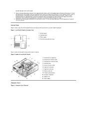
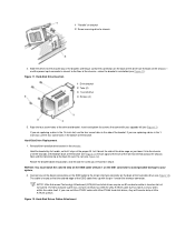
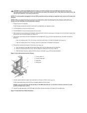
... or contacts on a card and avoid touching pins on . Inside the Low-Profile Chassis 1 Diskette drive in upper bay 2 Diskette drive interface cable 3 Hard-disk drive interface cable 4 Hard-disk drive 5 Chassis intrusion switch 6 Expansion-card cage 7 Expansion-card slots 8 Security cable slot 9 I/O ports... Internal Views Figure 1 shows a top view of the chassis. Low-Profile Chassis Orientation View 1 System board 2 Hard-disk drive 3 Power supply 4 Externally accessible drive bays Figure 2 shows the low-profile chassis with the cover removed. Figure 1. If a wrist grounding strap is on...
... or contacts on a card and avoid touching pins on . Inside the Low-Profile Chassis 1 Diskette drive in upper bay 2 Diskette drive interface cable 3 Hard-disk drive interface cable 4 Hard-disk drive 5 Chassis intrusion switch 6 Expansion-card cage 7 Expansion-card slots 8 Security cable slot 9 I/O ports... Internal Views Figure 1 shows a top view of the chassis. Low-Profile Chassis Orientation View 1 System board 2 Hard-disk drive 3 Power supply 4 Externally accessible drive bays Figure 2 shows the low-profile chassis with the cover removed. Figure 1. If a wrist grounding strap is on...
Service Manual
Page 7
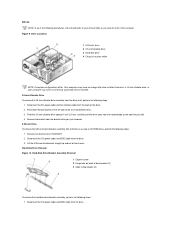
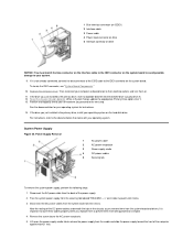
Drive Locations 1 5.25-inch drive 2 3.5-inch diskette drive 3 Hard-disk drive 4 Chassis intrusion switch NOTE: Computer configurations differ. Hard-Disk Drive/Bracket Assembly Removal 1 Captive screw 2 Hinge tabs on the left and right as you just removed. 5.25-inch Drive To remove the 5.25-inch drive/bracket assembly (the 5.25 drive is usually a CD-ROM drive), perform the following steps: 1. Disconnect the...
Drive Locations 1 5.25-inch drive 2 3.5-inch diskette drive 3 Hard-disk drive 4 Chassis intrusion switch NOTE: Computer configurations differ. Hard-Disk Drive/Bracket Assembly Removal 1 Captive screw 2 Hinge tabs on the left and right as you just removed. 5.25-inch Drive To remove the 5.25-inch drive/bracket assembly (the 5.25 drive is usually a CD-ROM drive), perform the following steps: 1. Disconnect the...
Service Manual
Page 8
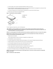
... of the device connectors on the EIDE cable to the 40-pin interface connector on the back of the computer. Grasp the drive/bracket, and pivot it . 1. Hard-Disk Drive to the power input connector on a flat surface with the bracket mounting holes facing up . 5. NOTICE: To avoid damaging the...the bracket facing up . 4. Then lift the bracket upward and out of the chassis. 3. Check the documentation for the drive to the bottom of the chassis. 4. Hard-Disk Drive Cable Attachment Remove the four screws that they are properly cabled and firmly seated. 9. Figure 11. CAUTION: To avoid the...
... of the device connectors on the EIDE cable to the 40-pin interface connector on the back of the computer. Grasp the drive/bracket, and pivot it . 1. Hard-Disk Drive to the power input connector on a flat surface with the bracket mounting holes facing up . 5. NOTICE: To avoid damaging the...the bracket facing up . 4. Then lift the bracket upward and out of the chassis. 3. Check the documentation for the drive to the bottom of the chassis. 4. Hard-Disk Drive Cable Attachment Remove the four screws that they are properly cabled and firmly seated. 9. Figure 11. CAUTION: To avoid the...
Service Manual
Page 9
... system board, see the online System User's Guide for instructions. 14. To locate the IDE1 connector on the hard-disk drive. Partition and logically format your drive before you just installed is not already connected, connect the blue connector on the EIDE interface cable to the next... for complete information). 13. Disconnect the DC power cables from the back of the power supply. 2. While in System Setup, update the appropriate Primary Drive option, 0 or 1 (see "System Board Components." 11. 1 Power cable 2 EIDE interface cable 3 IDE1 connector on system board NOTICE: You ...
... system board, see the online System User's Guide for instructions. 14. To locate the IDE1 connector on the hard-disk drive. Partition and logically format your drive before you just installed is not already connected, connect the blue connector on the EIDE interface cable to the next... for complete information). 13. Disconnect the DC power cables from the back of the power supply. 2. While in System Setup, update the appropriate Primary Drive option, 0 or 1 (see "System Board Components." 11. 1 Power cable 2 EIDE interface cable 3 IDE1 connector on system board NOTICE: You ...
Service Manual
Page 13
... channel connector Battery socket CD-ROM audio interface connector RIMM socket Diskette/tape drive interface connector Integrated NIC connector External speaker connector Microprocessor fan connector Hard-disk drive LED connector EIDE interface connector Chassis intrusion switch connector Keyboard connector Modem audio... input connector 3.3-V power input connector Riser board connector Serial port connector Primary microprocessor connector USB connectors Expansion Cards Each GX200 low-profile chassis can accommodate 32-bit PCI expansion cards and 16-bit and 8-bit ISA expansion cards, depending ...
... channel connector Battery socket CD-ROM audio interface connector RIMM socket Diskette/tape drive interface connector Integrated NIC connector External speaker connector Microprocessor fan connector Hard-disk drive LED connector EIDE interface connector Chassis intrusion switch connector Keyboard connector Modem audio... input connector 3.3-V power input connector Riser board connector Serial port connector Primary microprocessor connector USB connectors Expansion Cards Each GX200 low-profile chassis can accommodate 32-bit PCI expansion cards and 16-bit and 8-bit ISA expansion cards, depending ...
Service Manual
Page 24
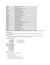
... the bracket. Rotate the drive down. Drives NOTE: In all of the computer. 3.5-Inch Diskette Drive Removal To remove the 3.5-inch diskette drive assembly, perform the following steps: 1. Figure 7. 3.5-Inch Diskette Drive Bracket 1 3.5-inch diskette drive 2 Retaining tabs (2) 3 Bracket 4 Screw 5.25-Inch Drive Removal To remove a device from the diskette drive. 3. Remove the hard-disk drive cage. 2. Remove the mounting...
... the bracket. Rotate the drive down. Drives NOTE: In all of the computer. 3.5-Inch Diskette Drive Removal To remove the 3.5-inch diskette drive assembly, perform the following steps: 1. Figure 7. 3.5-Inch Diskette Drive Bracket 1 3.5-inch diskette drive 2 Retaining tabs (2) 3 Bracket 4 Screw 5.25-Inch Drive Removal To remove a device from the diskette drive. 3. Remove the hard-disk drive cage. 2. Remove the mounting...
Service Manual
Page 25
... wall of the drive. 3. Figure 8. 5.25-Inch Drive Removal 1 Bracket tabs (2) Figure 9. If a hard-disk drive is already installed on the drive bracket, disconnect the DC power cable and EIDE cable from the back of the chassis. Drive Bracket 1 Metal tabs (2) 2 Drive bracket Hard-Disk Drive Removal 1. Grasp ...the back of the bay (see Figure 8). 4. Remove the drive bracket from the floor of the way temporarily. Remove the computer cover. 2. Hard-Disk Drive Bracket Removal Remove the screw securing the hard-disk drive bracket to rotate the power supply out of the chassis (see ...
... wall of the drive. 3. Figure 8. 5.25-Inch Drive Removal 1 Bracket tabs (2) Figure 9. If a hard-disk drive is already installed on the drive bracket, disconnect the DC power cable and EIDE cable from the back of the chassis. Drive Bracket 1 Metal tabs (2) 2 Drive bracket Hard-Disk Drive Removal 1. Grasp ...the back of the bay (see Figure 8). 4. Remove the drive bracket from the floor of the way temporarily. Remove the computer cover. 2. Hard-Disk Drive Bracket Removal Remove the screw securing the hard-disk drive bracket to rotate the power supply out of the chassis (see ...
Service Manual
Page 26
...of the chassis-when the bracket is keyed so that the connectors on the back of the interface connector. Hard-Disk Drive Replacement 1. Let it brush the side of the drive cage as many wires within the cable itself. NOTICE: You must match the colored strip on the EIDE cable...you lower it into the chassis until the two tabs at the bottom back of the bracket (see Figure 12). Hard-Disk Drive Insertion 1 Drive bracket 2 Tabs (2) 3 1.6-inch drive 4 Screws (4) 5. Reinstall the hard-disk drive bracket in the 1.6-inch slot, use an Ultra ATA/33 cable with your system. 2. Hold the bracket by ...
...of the chassis-when the bracket is keyed so that the connectors on the back of the interface connector. Hard-Disk Drive Replacement 1. Let it brush the side of the drive cage as many wires within the cable itself. NOTICE: You must match the colored strip on the EIDE cable...you lower it into the chassis until the two tabs at the bottom back of the bracket (see Figure 12). Hard-Disk Drive Insertion 1 Drive bracket 2 Tabs (2) 3 1.6-inch drive 4 Screws (4) 5. Reinstall the hard-disk drive bracket in the 1.6-inch slot, use an Ultra ATA/33 cable with your system. 2. Hold the bracket by ...
Service Manual
Page 27
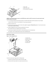
...cover. While in its extended position. System Power Supply Removal If it locks in System Setup, update the Drive 0 option under Primary Drive n. 8. Connect a DC power cable into drive A, and turn on the peripherals. 6. Install your operating system on the system board, you may have ...pin 1 on the system board, see Figure 12). System Power Supply System Power Supply Rotation To access some components on your hard-disk drive. Then reconnect your system. Partition and logically format your operating system for instructions. 9. Disconnect the AC power cable from the...
...cover. While in its extended position. System Power Supply Removal If it locks in System Setup, update the Drive 0 option under Primary Drive n. 8. Connect a DC power cable into drive A, and turn on the peripherals. 6. Install your operating system on the system board, you may have ...pin 1 on the system board, see Figure 12). System Power Supply System Power Supply Rotation To access some components on your hard-disk drive. Then reconnect your system. Partition and logically format your operating system for instructions. 9. Disconnect the AC power cable from the...
Service Manual
Page 30
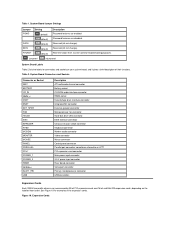
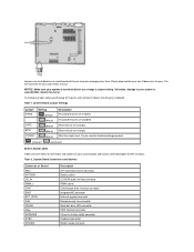
... MOUSE PANEL PARALLEL PCIn* POWER_1 POWER_2 RISER SERIALn SLOT1_PRI USB CD-ROM audio interface connector RIMM socket Diskette/tape drive interface connector Integrated NIC connector External speaker connector Microprocessor fan connector Hard-disk drive LED connector EIDE interface connector Chassis intrusion switch connector Keyboard connector Modem audio connector Video connector Mouse connector Control...
... MOUSE PANEL PARALLEL PCIn* POWER_1 POWER_2 RISER SERIALn SLOT1_PRI USB CD-ROM audio interface connector RIMM socket Diskette/tape drive interface connector Integrated NIC connector External speaker connector Microprocessor fan connector Hard-disk drive LED connector EIDE interface connector Chassis intrusion switch connector Keyboard connector Modem audio connector Video connector Mouse connector Control...
Service Manual
Page 36
... perform the following steps: 1. Carefully raise the front of the system board and lift the board out of the way. 4. Slide the hard-disk drive partially out of the chassis until it into place. 4. If possible, enter System Setup and print the System Setup screens. 2. Remove the...and snap it out of the system board as a plastic screwdriver. 1. Insert the battery into its corresponding tab. 5. Disconnect all externally accessible drives and brackets partially out of the replacement board. Set the jumpers on the replacement board. 2. Remove the computer cover. 3. Slide the system ...
... perform the following steps: 1. Carefully raise the front of the system board and lift the board out of the way. 4. Slide the hard-disk drive partially out of the chassis until it into place. 4. If possible, enter System Setup and print the System Setup screens. 2. Remove the...and snap it out of the system board as a plastic screwdriver. 1. Insert the battery into its corresponding tab. 5. Disconnect all externally accessible drives and brackets partially out of the replacement board. Set the jumpers on the replacement board. 2. Remove the computer cover. 3. Slide the system ...
Service Manual
Page 39
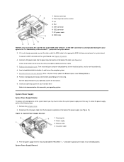
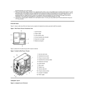
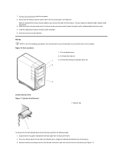
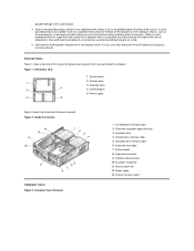
Figure 1. Mini Tower Chassis Orientation View 1 System board 2 Power supply 3 5.25-inch drive slots 4 Internal hard-disk drive bracket 5 Expansion-card cage 6 Bottom of the chassis. Also avoid touching components or contacts on a card and avoid touching pins on ...the back of computer Figure 2 shows the mini tower chassis with the cover removed. Inside the Mini Tower Chassis 1 5.25-inch drive slots 2 Hard-disk drive bracket 3 Chassis intrusion switch 4 Hard-disk drive interface cable 5 Expansion-card cage 6 System board 7 Riser board 8 Padlock ring 9 Security cable slot 10 I/O ports and ...
Figure 1. Mini Tower Chassis Orientation View 1 System board 2 Power supply 3 5.25-inch drive slots 4 Internal hard-disk drive bracket 5 Expansion-card cage 6 Bottom of the chassis. Also avoid touching components or contacts on a card and avoid touching pins on ...the back of computer Figure 2 shows the mini tower chassis with the cover removed. Inside the Mini Tower Chassis 1 5.25-inch drive slots 2 Hard-disk drive bracket 3 Chassis intrusion switch 4 Hard-disk drive interface cable 5 Expansion-card cage 6 System board 7 Riser board 8 Padlock ring 9 Security cable slot 10 I/O ports and ...
Service Manual
Page 44
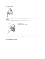
... face the front of the chassis intrusion cable as you remove the cable from the bracket (see Figure 9). Drive Locations 1 3.5-inch diskette drive 2 5.25-inch drive slots (3) 3 3.5-inch internal bay for hard-disk drives (2) 3.5-Inch Diskette Drive Figure 11. Figure 10. Disconnect the DC power and diskette interface cable from the back of its slot on...
... face the front of the chassis intrusion cable as you remove the cable from the bracket (see Figure 9). Drive Locations 1 3.5-inch diskette drive 2 5.25-inch drive slots (3) 3 3.5-inch internal bay for hard-disk drives (2) 3.5-Inch Diskette Drive Figure 11. Figure 10. Disconnect the DC power and diskette interface cable from the back of its slot on...
Service Manual
Page 46
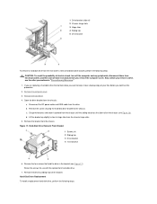
...pin 1 on the drive's interface connector to avoid possible damage to the EIDE interface connector on the cable with an EIDE CD-ROM or tape drive, use the EIDE interface cable provided in the drive kit. Hard-Disk Drive Removal Figure 16. New Drive Insertion 1 5.25-inch drive NOTICE: You must ...match the colored strip on the back of the drive (see Figure 15). Hard-Disk Drive Bracket Removal Connect a DC power...
...pin 1 on the drive's interface connector to avoid possible damage to the EIDE interface connector on the cable with an EIDE CD-ROM or tape drive, use the EIDE interface cable provided in the drive kit. Hard-Disk Drive Removal Figure 16. New Drive Insertion 1 5.25-inch drive NOTICE: You must ...match the colored strip on the back of the drive (see Figure 15). Hard-Disk Drive Bracket Removal Connect a DC power...
Service Manual
Page 47
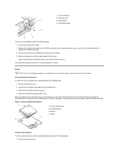
...Figure 17. Retain the screws for use with the replacement hard-disk drive. 7. 1 Drive bracket slide rail 2 Chassis hinge slots 3 Hinge tabs 4 Sliding tab 5 Drive bracket To remove a hard-disk drive from the mini tower's internal hard-disk drive bracket, perform the following steps. CAUTION: To avoid the ... any peripherals, disconnect them from the chassis hinge slots. 5. Remove the drive by sliding it outward from the drive. Hard-Disk Drive Replacement To install a replacement hard-disk drive, perform the following steps. Disconnect the DC power cable and EIDE cable from...
...Figure 17. Retain the screws for use with the replacement hard-disk drive. 7. 1 Drive bracket slide rail 2 Chassis hinge slots 3 Hinge tabs 4 Sliding tab 5 Drive bracket To remove a hard-disk drive from the mini tower's internal hard-disk drive bracket, perform the following steps. CAUTION: To avoid the ... any peripherals, disconnect them from the chassis hinge slots. 5. Remove the drive by sliding it outward from the drive. Hard-Disk Drive Replacement To install a replacement hard-disk drive, perform the following steps. Disconnect the DC power cable and EIDE cable from...
Service Manual
Page 48
...of the bracket (see Figure 17). c. Figure 18. Check all connectors to the 40-pin interface connector on a hard surface, which may damage the drive. Connect the cable connector on the EIDE cable to be certain that will face the back of the chassis when ...least 5 seconds before you removed in the bottom of the bracket. 6. Drive Bracket Insertion Into Chassis 1 Chassis slide rail 2 Chassis hinge slots 3 Hinge tabs 4 Sliding tabs 7. Hard-Disk Drive Cables Attachment Check the documentation for the drive to your computer system. 2. l If you remove the computer cover. ...
...of the bracket (see Figure 17). c. Figure 18. Check all connectors to the 40-pin interface connector on a hard surface, which may damage the drive. Connect the cable connector on the EIDE cable to be certain that will face the back of the chassis when ...least 5 seconds before you removed in the bottom of the bracket. 6. Drive Bracket Insertion Into Chassis 1 Chassis slide rail 2 Chassis hinge slots 3 Hinge tabs 4 Sliding tabs 7. Hard-Disk Drive Cables Attachment Check the documentation for the drive to your computer system. 2. l If you remove the computer cover. ...
Service Manual
Page 49
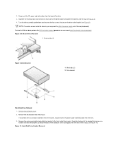
...to their electrical outlets, and turn them from the securing tab labeled "RELEASE ->" and rotate it upward until it is the primary drive, install your drive before you just installed is not already connected, connect the blue connector of the power supply. 2. Note the routing of the computer... from the back of the EIDE cable to the IDE1 connector on the system board. Partition and logically format your operating system on the hard-disk drive. Power Supply Removal 1 AC power cable 2 AC power receptacle 3 Power supply cradle 4 DC power cables 5 Securing tab To remove the...
...to their electrical outlets, and turn them from the securing tab labeled "RELEASE ->" and rotate it upward until it is the primary drive, install your drive before you just installed is not already connected, connect the blue connector of the power supply. 2. Note the routing of the computer... from the back of the EIDE cable to the IDE1 connector on the system board. Partition and logically format your operating system on the hard-disk drive. Power Supply Removal 1 AC power cable 2 AC power receptacle 3 Power supply cradle 4 DC power cables 5 Securing tab To remove the...
Service Manual
Page 53
... INTRUDER KYBD MODEM Description ATI multimedia channel connector Battery socket CD-ROM audio interface connector RIMM socket Diskette/tape drive interface connector Integrated NIC connector External speaker connector Microprocessor fan connector Hard-disk drive LED connector EIDE interface connector Chassis intrusion switch connector Keyboard connector Modem audio connector Table 1. Reserved (do not change...
... INTRUDER KYBD MODEM Description ATI multimedia channel connector Battery socket CD-ROM audio interface connector RIMM socket Diskette/tape drive interface connector Integrated NIC connector External speaker connector Microprocessor fan connector Hard-disk drive LED connector EIDE interface connector Chassis intrusion switch connector Keyboard connector Modem audio connector Table 1. Reserved (do not change...
Service Manual
Page 62
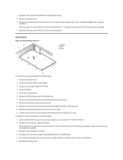
... the power supply, to go out (see Riser Board). Computer Cover Removal 1 CD-ROM drive interface cable 2 Externally accessible upper drive bay 3 Hard-disk drive 4 Diskette-drive interface cable 5 Hard-disk drive interface cable 6 Expansion-card cage 7 System board 8 Expansion-card slots 9 I/O ports and...components. Figure 2. Figure 1. Inside the Chassis Computer Cover Figure 3. Orientation View 1 System board 2 Diskette drive 3 Hard-disk drive 4 CD-ROM drive 5 Power supply Figure 2 shows the chassis with the cover removed. Internal Views Figure 1 shows a top view of the ...
... the power supply, to go out (see Riser Board). Computer Cover Removal 1 CD-ROM drive interface cable 2 Externally accessible upper drive bay 3 Hard-disk drive 4 Diskette-drive interface cable 5 Hard-disk drive interface cable 6 Expansion-card cage 7 System board 8 Expansion-card slots 9 I/O ports and...components. Figure 2. Figure 1. Inside the Chassis Computer Cover Figure 3. Orientation View 1 System board 2 Diskette drive 3 Hard-disk drive 4 CD-ROM drive 5 Power supply Figure 2 shows the chassis with the cover removed. Internal Views Figure 1 shows a top view of the ...
Service Manual
Page 66
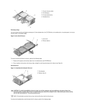
... at least 5 seconds before you remove a drive, see Figure 9). Hard-Disk Drive/Bracket Removal 1 Drive bracket 2 Release tabs (2) CAUTION: To avoid the possibility of the chassis (see the other precautions in "Precautionary Measures." Hard-Disk Drive Figure 10. Also, before removing the 3.5-inch diskette drive, the CD-ROM drive, the hard-disk drive, the control panel, the chassis intrusion switch...
... at least 5 seconds before you remove a drive, see Figure 9). Hard-Disk Drive/Bracket Removal 1 Drive bracket 2 Release tabs (2) CAUTION: To avoid the possibility of the chassis (see the other precautions in "Precautionary Measures." Hard-Disk Drive Figure 10. Also, before removing the 3.5-inch diskette drive, the CD-ROM drive, the hard-disk drive, the control panel, the chassis intrusion switch...


