Service Manual
Page 4
... Tower Computer 1-22 Hard-Disk Drive for the OptiPlex NX1 Computer 1-22 Power-Supply Service Data 1-22 Pin Assignments for the DC Power Connectors 1-23 DC Power Distribution 1-24 System Power Supply for the OptiPlex NX1 Computer 1-29 OptiPlex NX1 Pin Assignments for the DC Power Connectors . . 1-30 DC Power Distribution for the OptiPlex NX1 Computer 1-31 Technical Specifications 1-33 Initial User...
... Tower Computer 1-22 Hard-Disk Drive for the OptiPlex NX1 Computer 1-22 Power-Supply Service Data 1-22 Pin Assignments for the DC Power Connectors 1-23 DC Power Distribution 1-24 System Power Supply for the OptiPlex NX1 Computer 1-29 OptiPlex NX1 Pin Assignments for the DC Power Connectors . . 1-30 DC Power Distribution for the OptiPlex NX1 Computer 1-31 Technical Specifications 1-33 Initial User...

Service Manual
Page 5
... Control Panel 4-6 Drives 4-7 Externally Accessible Drive Assemblies 4-7 3.5-Inch Diskette Drive Assembly 4-8 5.25-Inch Drive Assembly 4-9 Hard-Disk Drive Assembly 4-10 System Power Supply 4-11 Expansion Cards 4-12 Expansion-Card Cage 4-12 Expansion Card 4-13 Riser Board 4-14 System Board 4-15 System Board Components 4-16 DIMMs 4-17 Video...Heat Sink Assembly 4-19 System Battery 4-20 Recommended Tools 5-1 Precautionary Measures 5-1 Inside the Computer 5-2 Optional Stand 5-4 Computer Cover 5-5 Eject, Power, and Reset Buttons 5-6 Front-Panel Inserts 5-7 Control Panel 5-8 vii
... Control Panel 4-6 Drives 4-7 Externally Accessible Drive Assemblies 4-7 3.5-Inch Diskette Drive Assembly 4-8 5.25-Inch Drive Assembly 4-9 Hard-Disk Drive Assembly 4-10 System Power Supply 4-11 Expansion Cards 4-12 Expansion-Card Cage 4-12 Expansion Card 4-13 Riser Board 4-14 System Board 4-15 System Board Components 4-16 DIMMs 4-17 Video...Heat Sink Assembly 4-19 System Battery 4-20 Recommended Tools 5-1 Precautionary Measures 5-1 Inside the Computer 5-2 Optional Stand 5-4 Computer Cover 5-5 Eject, Power, and Reset Buttons 5-6 Front-Panel Inserts 5-7 Control Panel 5-8 vii

Service Manual
Page 6
... Accessible Drive Assemblies 5-9 3.5-Inch Diskette Drive Assembly 5-10 5.25-Inch Drive Assembly 5-11 Hard-Disk Drive Bracket 5-12 Hard-Disk Drive 5-13 System Power Supply 5-14 Expansion Cards 5-15 Expansion-Card Cage 5-15 Expansion Card 5-16 Riser Board 5-17 System Board 5-18 System Board Components 5-19 DIMMs 5-20 Video...6-10 3.5-Inch Diskette Drive Assembly 6-11 5.25-Inch Drive Assembly 6-12 Hard-Disk Drive Bracket 6-14 Hard-Disk Drive 6-15 System Power Supply 6-16 Expansion Cards 6-17 Expansion-Card Cage 6-17 Expansion Card 6-18 Riser Board 6-19 System Board 6-20 viii
... Accessible Drive Assemblies 5-9 3.5-Inch Diskette Drive Assembly 5-10 5.25-Inch Drive Assembly 5-11 Hard-Disk Drive Bracket 5-12 Hard-Disk Drive 5-13 System Power Supply 5-14 Expansion Cards 5-15 Expansion-Card Cage 5-15 Expansion Card 5-16 Riser Board 5-17 System Board 5-18 System Board Components 5-19 DIMMs 5-20 Video...6-10 3.5-Inch Diskette Drive Assembly 6-11 5.25-Inch Drive Assembly 6-12 Hard-Disk Drive Bracket 6-14 Hard-Disk Drive 6-15 System Power Supply 6-16 Expansion Cards 6-17 Expansion-Card Cage 6-17 Expansion Card 6-18 Riser Board 6-19 System Board 6-20 viii

Service Manual
Page 7
...24 System Battery 6-25 Recommended Tools 7-1 Precautionary Measures 7-1 Inside the Computer 7-2 Optional Stand 7-3 Computer Cover 7-4 Control Panel 7-6 Hard-Disk Drive 7-7 System Power Supply 7-8 Expansion-Card Cage 7-9 Expansion Card 7-10 Riser Board 7-11 System Board 7-12 System Board Components 7-13 DIMMs 7-14 Video Memory 7-15 Microprocessor 7-16...Internal View of the Midsize Chassis 1-10 Internal View of the Mini Tower Chassis 1-11 Internal View of the OptiPlex NX1 Chassis 1-12 Riser Board for the OptiPlex NX1 Computer 1-13 ix Figure 1-4. Figure 1-2. Figure 1-3.
...24 System Battery 6-25 Recommended Tools 7-1 Precautionary Measures 7-1 Inside the Computer 7-2 Optional Stand 7-3 Computer Cover 7-4 Control Panel 7-6 Hard-Disk Drive 7-7 System Power Supply 7-8 Expansion-Card Cage 7-9 Expansion Card 7-10 Riser Board 7-11 System Board 7-12 System Board Components 7-13 DIMMs 7-14 Video Memory 7-15 Microprocessor 7-16...Internal View of the Midsize Chassis 1-10 Internal View of the Mini Tower Chassis 1-11 Internal View of the OptiPlex NX1 Chassis 1-12 Riser Board for the OptiPlex NX1 Computer 1-13 ix Figure 1-4. Figure 1-2. Figure 1-3.
Service Manual
Page 8
... Diskette Drive to the OptiPlex NX1 Computer 2-9 Internal View of the Low-Profile Computer 4-3 Computer Cover Removal 4-3 Eject, Power, and Reset Button Removal 4-4 Front-Panel Insert Removal 4-5 Control Panel Removal 4-6 Drive Hardware 4-7 3.5-Inch Diskette Drive Removal 4-8 5.25-Inch Drive Assembly Removal 4-9 Hard-Disk Drive Assembly Removal 4-10 System Power-Supply Removal 4-11 Expansion-Card...
... Diskette Drive to the OptiPlex NX1 Computer 2-9 Internal View of the Low-Profile Computer 4-3 Computer Cover Removal 4-3 Eject, Power, and Reset Button Removal 4-4 Front-Panel Insert Removal 4-5 Control Panel Removal 4-6 Drive Hardware 4-7 3.5-Inch Diskette Drive Removal 4-8 5.25-Inch Drive Assembly Removal 4-9 Hard-Disk Drive Assembly Removal 4-10 System Power-Supply Removal 4-11 Expansion-Card...
Service Manual
Page 9
...Heat Sink Removal 4-19 System Battery Installation 4-20 Internal View of the Midsize Computer 5-3 Optional-Stand Removal 5-4 Computer Cover Removal 5-5 Eject, Power, and Reset Button Removal 5-6 Front-Panel Insert Removal 5-7 Control Panel Removal 5-8 Drive Hardware 5-9 3.5-Inch Diskette Drive Removal 5-10 5.25...Assembly Removal 5-11 5.25-Inch Drive Removal 5-11 Hard-Disk Drive Bracket Removal 5-12 Hard-Disk Drive Removal 5-13 System Power-Supply Removal 5-14 Expansion-Card Cage Removal 5-15 Expansion-Card Removal 5-16 Riser Board Removal 5-17 System Board Removal 5-18 System ...
...Heat Sink Removal 4-19 System Battery Installation 4-20 Internal View of the Midsize Computer 5-3 Optional-Stand Removal 5-4 Computer Cover Removal 5-5 Eject, Power, and Reset Button Removal 5-6 Front-Panel Insert Removal 5-7 Control Panel Removal 5-8 Drive Hardware 5-9 3.5-Inch Diskette Drive Removal 5-10 5.25...Assembly Removal 5-11 5.25-Inch Drive Removal 5-11 Hard-Disk Drive Bracket Removal 5-12 Hard-Disk Drive Removal 5-13 System Power-Supply Removal 5-14 Expansion-Card Cage Removal 5-15 Expansion-Card Removal 5-16 Riser Board Removal 5-17 System Board Removal 5-18 System ...
Service Manual
Page 10
... Module 6-23 SEC Cartridge/Heat Sink Removal 6-24 System Battery Installation 6-25 Internal View of the OptiPlex NX1 Computer 7-3 Optional-Stand Removal 7-3 Computer Cover Removal 7-4 Service Access Lock 7-5 Control Panel Removal 7-6 Hard-Disk Drive Removal 7-7 System Power-Supply Removal 7-8 Expansion-Card Cage Removal 7-9 Expansion-Card Removal 7-10 Riser Board Removal 7-11 System Board...
... Module 6-23 SEC Cartridge/Heat Sink Removal 6-24 System Battery Installation 6-25 Internal View of the OptiPlex NX1 Computer 7-3 Optional-Stand Removal 7-3 Computer Cover Removal 7-4 Service Access Lock 7-5 Control Panel Removal 7-6 Hard-Disk Drive Removal 7-7 System Power-Supply Removal 7-8 Expansion-Card Cage Removal 7-9 Expansion-Card Removal 7-10 Riser Board Removal 7-11 System Board...
Service Manual
Page 14
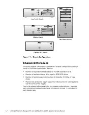
...OptiPlex NX1 chassis configurations differ primarily in the following expansion features: Number of expansion slots available for PCI/ISA expansion cards Number of available internal drive bays for EIDE/SCSI drives Number of available external drive bays for diskette, CD-ROM, or tape drives Physical size and power supply... types (the midsize and mini tower systems use the same power supply) Due to the physical differences in the four chassis configurations, a separate parts removal and ...
...OptiPlex NX1 chassis configurations differ primarily in the following expansion features: Number of expansion slots available for PCI/ISA expansion cards Number of available internal drive bays for EIDE/SCSI drives Number of available external drive bays for diskette, CD-ROM, or tape drives Physical size and power supply... types (the midsize and mini tower systems use the same power supply) Due to the physical differences in the four chassis configurations, a separate parts removal and ...

Service Manual
Page 19
... Integrated Devices," in the U.S. Figures 1-3 through 1-6 for I/O port identifiers for attaching to the online Network Administrator's Guide. System Overview 1-7 Dell OptiPlex GX1 and OptiPlex NX1 systems have a special power supply that can operate from standard AC power outlets in the Reference and Installation Guide provides instructions for connecting the computer to an RJ45 port on a UTP...
... Integrated Devices," in the U.S. Figures 1-3 through 1-6 for I/O port identifiers for attaching to the online Network Administrator's Guide. System Overview 1-7 Dell OptiPlex GX1 and OptiPlex NX1 systems have a special power supply that can operate from standard AC power outlets in the Reference and Installation Guide provides instructions for connecting the computer to an RJ45 port on a UTP...

Service Manual
Page 21
power supply padlock ring voltage selection switch AC power receptacle parallel port connector serial port 1 connector mouse connector keyboard connector USB connectors (2) serial port 2 connector 3.5-inch diskette drive diskette/tape drive interface cable hard-disk drive interface cable hard-disk drive chassis intrusion switch audio connectors (3) NIC connector (optional) video connector security cable slot expansion-card cage expansion-card slots (3) System Overview 1-9
power supply padlock ring voltage selection switch AC power receptacle parallel port connector serial port 1 connector mouse connector keyboard connector USB connectors (2) serial port 2 connector 3.5-inch diskette drive diskette/tape drive interface cable hard-disk drive interface cable hard-disk drive chassis intrusion switch audio connectors (3) NIC connector (optional) video connector security cable slot expansion-card cage expansion-card slots (3) System Overview 1-9

Service Manual
Page 22
3.5-inch diskette drive diskette/tape drive interface cable drive cage power supply hard-disk drive bracket AC power receptacle voltage selection switch padlock ring chassis intrusion switch hard-disk drive interface cable parallel port connector serial port 1 connector mouse connector keyboard connector USB connectors (2) serial port 2 connector expansion-card cage expansion-card slots (5) NIC connector (optional) video connector security cable slot audio connectors (3) 1-10
3.5-inch diskette drive diskette/tape drive interface cable drive cage power supply hard-disk drive bracket AC power receptacle voltage selection switch padlock ring chassis intrusion switch hard-disk drive interface cable parallel port connector serial port 1 connector mouse connector keyboard connector USB connectors (2) serial port 2 connector expansion-card cage expansion-card slots (5) NIC connector (optional) video connector security cable slot audio connectors (3) 1-10

Service Manual
Page 23
AC power receptacle security cable slot parallel port connector serial port 1 connector keyboard connector mouse connector USB connectors (2) serial port 2 connector video connector NIC connector (optional) audio connectors (3) padlock ring power supply external drive bays hard-disk drive bracket interface cable chassis intrusion switch expansion-card cage system board riser board System Overview 1-11
AC power receptacle security cable slot parallel port connector serial port 1 connector keyboard connector mouse connector USB connectors (2) serial port 2 connector video connector NIC connector (optional) audio connectors (3) padlock ring power supply external drive bays hard-disk drive bracket interface cable chassis intrusion switch expansion-card cage system board riser board System Overview 1-11

Service Manual
Page 24
... security access lock chassis intrusion switch power supply DC power cable EIDE cable parallel port connector serial port 1 connector mouse connector keyboard connector USB connectors (2) serial port 2 connector hard-disk drive expansion-card cage expansion-card slot security cable slot AC power receptacle NIC connector (optional) video connector The OptiPlex GX1 systems contain advanced expansion...
... security access lock chassis intrusion switch power supply DC power cable EIDE cable parallel port connector serial port 1 connector mouse connector keyboard connector USB connectors (2) serial port 2 connector hard-disk drive expansion-card cage expansion-card slot security cable slot AC power receptacle NIC connector (optional) video connector The OptiPlex GX1 systems contain advanced expansion...

Service Manual
Page 34
... the DC operating voltages and currents listed in Table 1-4. NOTE: The power supply produces DC voltages only under its loaded condition. All system power supplies can operate from an AC power source of 115 VAC at 50 to 60 Hz or 230 VAC at the front of the computer. Therefore, ... externally accessible drive bays at 50 to 60 Hz. The low-profile computers have a 145-W system power supply, the midsize computers have a 200-W system power supply, and the mini tower computers have a 230-W power supply. One 1-inch-high EIDE hard-disk drive can contain either one or two 1-inch-high EIDE or...
... the DC operating voltages and currents listed in Table 1-4. NOTE: The power supply produces DC voltages only under its loaded condition. All system power supplies can operate from an AC power source of 115 VAC at 50 to 60 Hz or 230 VAC at the front of the computer. Therefore, ... externally accessible drive bays at 50 to 60 Hz. The low-profile computers have a 145-W system power supply, the midsize computers have a 200-W system power supply, and the mini tower computers have a 230-W power supply. One 1-inch-high EIDE hard-disk drive can contain either one or two 1-inch-high EIDE or...

Service Manual
Page 35
PWRGOOD should measure between +4 and +5 VDC when the power supply is pressed, taking PSON# to indicate that all power-supply output voltages are within ranges specified in Table 1-4. System Overview 1-23 The power-supply output voltages can be measured at the back (wire side) of the connectors. -5 VDC (white) ... -4.50 to -5.50 VDC 0.3 A (low-profile computers); 0.3 A (midsize and mini tower computers) +5 VFP3 +4.75 to control the power-supply fan speed. 3 Pin 5 - Figures 1-15 through 1-17 show the wire side of the connectors without disconnecting them. sometimes called "standby...
PWRGOOD should measure between +4 and +5 VDC when the power supply is pressed, taking PSON# to indicate that all power-supply output voltages are within ranges specified in Table 1-4. System Overview 1-23 The power-supply output voltages can be measured at the back (wire side) of the connectors. -5 VDC (white) ... -4.50 to -5.50 VDC 0.3 A (low-profile computers); 0.3 A (midsize and mini tower computers) +5 VFP3 +4.75 to control the power-supply fan speed. 3 Pin 5 - Figures 1-15 through 1-17 show the wire side of the connectors without disconnecting them. sometimes called "standby...
Service Manual
Page 36
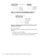
1234 P2, P3, P5, P6, P9 +5 VDC (red) common (black) common (black) +12 VDC (yellow) P4 12 34 +12 VDC (yellow) common (black) common (black) +5 VDC (red) P2, P7 1 2 34 5 6 +3.3 VDC (blue/white) +3.3 VDC (blue/white) +3.3 VDC (blue/white) common (black) common (black) common (black) Figures 1-18 through 1-22 provide the following information about DC power distribution: Power-supply connector identification Power cable connections for diskette, tape, CD-ROM, and hard-disk drives Power distribution to sockets and connectors on the system board 1-24
1234 P2, P3, P5, P6, P9 +5 VDC (red) common (black) common (black) +12 VDC (yellow) P4 12 34 +12 VDC (yellow) common (black) common (black) +5 VDC (red) P2, P7 1 2 34 5 6 +3.3 VDC (blue/white) +3.3 VDC (blue/white) +3.3 VDC (blue/white) common (black) common (black) common (black) Figures 1-18 through 1-22 provide the following information about DC power distribution: Power-supply connector identification Power cable connections for diskette, tape, CD-ROM, and hard-disk drives Power distribution to sockets and connectors on the system board 1-24

Service Manual
Page 40
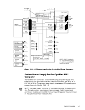
keyboard controller system board +3 VDC battery P1 PWRGOOD power management RTC/ and NIC logic NVRAM POWER1 system power supply PSON# +5 VFP +5 VDC -5 VDC +12 VDC -12 VDC P7 +3.3 VDC PSON# +5 VFP +5 VDC -5 VDC +12 VDC -12 VDC POWER2 +5 VDC -5 VDC +12 VDC -12 VDC ...
keyboard controller system board +3 VDC battery P1 PWRGOOD power management RTC/ and NIC logic NVRAM POWER1 system power supply PSON# +5 VFP +5 VDC -5 VDC +12 VDC -12 VDC P7 +3.3 VDC PSON# +5 VFP +5 VDC -5 VDC +12 VDC -12 VDC POWER2 +5 VDC -5 VDC +12 VDC -12 VDC ...
Service Manual
Page 41
... OptiPlex NX1 computers have an 80-W computer power supply. The power supply can operate from an AC power source of 115 VAC at 60 Hz or 230 VAC at 50 Hz. Therefore, when you measure these voltages, the DC power input connectors must be connected to P1 on the system board and hard-disk drive. The system power supply...
... OptiPlex NX1 computers have an 80-W computer power supply. The power supply can operate from an AC power source of 115 VAC at 60 Hz or 230 VAC at 50 Hz. Therefore, when you measure these voltages, the DC power input connectors must be connected to P1 on the system board and hard-disk drive. The system power supply...

Service Manual
Page 42
... to +5.25 VDC 1.2 A 1 The combined load on the +5-VDC and +3.3-VDC outputs should not exceed 65 W. 2 Withstands surges of the connectors without disconnecting them. The power-supply output voltages can be measured at the back (wire side) of up to 3.0 A to its active-low state. 2 Pin 19 - Thermal fan-speed control (TFSC...
... to +5.25 VDC 1.2 A 1 The combined load on the +5-VDC and +3.3-VDC outputs should not exceed 65 W. 2 Withstands surges of the connectors without disconnecting them. The power-supply output voltages can be measured at the back (wire side) of up to 3.0 A to its active-low state. 2 Pin 19 - Thermal fan-speed control (TFSC...

Service Manual
Page 43
P2 1 2 34 5 6 +3.3 VDC (blue/white) +3.3 VDC (blue/white) +3.3 VDC (blue/white) common (black) common (black) common (black) 1234 P3 +5 VDC (red) common (black) common (black) +12 VDC (yellow) Figures 1-26 and 1-27 provide the following information about DC power distribution: Power-supply connector identification Power cable connection for the hard-disk drive Power distribution to sockets and connectors on the system board P3 P2 P1 System Overview 1-31
P2 1 2 34 5 6 +3.3 VDC (blue/white) +3.3 VDC (blue/white) +3.3 VDC (blue/white) common (black) common (black) common (black) 1234 P3 +5 VDC (red) common (black) common (black) +12 VDC (yellow) Figures 1-26 and 1-27 provide the following information about DC power distribution: Power-supply connector identification Power cable connection for the hard-disk drive Power distribution to sockets and connectors on the system board P3 P2 P1 System Overview 1-31


