Service Manual
Page 4
... Channel Assignments 1-20 Hard-Disk Drive Service Information 1-20 Hard-Disk Drive for the Low-Profile Computer 1-21 Hard-Disk Drive for the Midsize Computer 1-21 Hard-Disk Drive for the Mini Tower Computer 1-22 Hard-Disk Drive for the OptiPlex NX1 Computer 1-22 ... Eliminating Resource Conflicts 2-5 Running the System Diagnostics 2-6 Server-Based Diagnostics 2-6 Hard-Disk-Based Diagnostics (OptiPlex NX1 Systems Only 2-7 Diskette-Based Diagnostics 2-9 Connecting an External Diskette Drive to the OptiPlex NX1 Computer 2-9 Running the Diskette-Based Diagnostics 2-10 Getting Help 2-11 ...
... Channel Assignments 1-20 Hard-Disk Drive Service Information 1-20 Hard-Disk Drive for the Low-Profile Computer 1-21 Hard-Disk Drive for the Midsize Computer 1-21 Hard-Disk Drive for the Mini Tower Computer 1-22 Hard-Disk Drive for the OptiPlex NX1 Computer 1-22 ... Eliminating Resource Conflicts 2-5 Running the System Diagnostics 2-6 Server-Based Diagnostics 2-6 Hard-Disk-Based Diagnostics (OptiPlex NX1 Systems Only 2-7 Diskette-Based Diagnostics 2-9 Connecting an External Diskette Drive to the OptiPlex NX1 Computer 2-9 Running the Diskette-Based Diagnostics 2-10 Getting Help 2-11 ...

Service Manual
Page 5
Recommended Tools 4-1 Precautionary Measures 4-1 Inside the Computer 4-2 Computer Cover 4-3 Eject, Power, and Reset Buttons 4-4 Front-Panel Inserts 4-5 Control Panel 4-6 Drives 4-7 Externally Accessible Drive Assemblies 4-7 3.5-Inch Diskette Drive Assembly 4-8 5.25-Inch Drive Assembly 4-9 Hard-Disk Drive Assembly 4-10 System Power Supply 4-11 Expansion Cards 4-12 Expansion-Card Cage 4-12 Expansion Card 4-13 Riser Board 4-14 System Board 4-15...
Recommended Tools 4-1 Precautionary Measures 4-1 Inside the Computer 4-2 Computer Cover 4-3 Eject, Power, and Reset Buttons 4-4 Front-Panel Inserts 4-5 Control Panel 4-6 Drives 4-7 Externally Accessible Drive Assemblies 4-7 3.5-Inch Diskette Drive Assembly 4-8 5.25-Inch Drive Assembly 4-9 Hard-Disk Drive Assembly 4-10 System Power Supply 4-11 Expansion Cards 4-12 Expansion-Card Cage 4-12 Expansion Card 4-13 Riser Board 4-14 System Board 4-15...

Service Manual
Page 6
Drives 5-9 Externally Accessible Drive Assemblies 5-9 3.5-Inch Diskette Drive Assembly 5-10 5.25-Inch Drive Assembly 5-11 Hard-Disk Drive Bracket 5-12 Hard-Disk Drive 5-13 System Power Supply 5-14 Expansion Cards 5-15 Expansion-Card Cage 5-15 Expansion ... Eject, Power, and Reset Buttons 6-6 Front-Panel Inserts 6-7 Control Panel 6-9 Drives 6-10 Externally Accessible Drive Assemblies 6-10 3.5-Inch Diskette Drive Assembly 6-11 5.25-Inch Drive Assembly 6-12 Hard-Disk Drive Bracket 6-14 Hard-Disk Drive 6-15 System Power Supply 6-16 Expansion Cards 6-17 Expansion-Card Cage 6-17 ...
Drives 5-9 Externally Accessible Drive Assemblies 5-9 3.5-Inch Diskette Drive Assembly 5-10 5.25-Inch Drive Assembly 5-11 Hard-Disk Drive Bracket 5-12 Hard-Disk Drive 5-13 System Power Supply 5-14 Expansion Cards 5-15 Expansion-Card Cage 5-15 Expansion ... Eject, Power, and Reset Buttons 6-6 Front-Panel Inserts 6-7 Control Panel 6-9 Drives 6-10 Externally Accessible Drive Assemblies 6-10 3.5-Inch Diskette Drive Assembly 6-11 5.25-Inch Drive Assembly 6-12 Hard-Disk Drive Bracket 6-14 Hard-Disk Drive 6-15 System Power Supply 6-16 Expansion Cards 6-17 Expansion-Card Cage 6-17 ...

Service Manual
Page 7
... the Midsize Chassis 1-10 Internal View of the Mini Tower Chassis 1-11 Internal View of the OptiPlex NX1 Chassis 1-12 Riser Board for the OptiPlex NX1 Computer 1-13 ix Figure 1-5. System Board Components 6-21 DIMMs 6-22 Video Memory 6-23 Microprocessor... 6-24 SEC Cartridge/Heat Sink Assembly 6-24 System Battery 6-25 Recommended Tools 7-1 Precautionary Measures 7-1 Inside the Computer 7-2 Optional Stand 7-3 Computer Cover 7-4 Control Panel 7-6 Hard-Disk Drive ...
... the Midsize Chassis 1-10 Internal View of the Mini Tower Chassis 1-11 Internal View of the OptiPlex NX1 Chassis 1-12 Riser Board for the OptiPlex NX1 Computer 1-13 ix Figure 1-5. System Board Components 6-21 DIMMs 6-22 Video Memory 6-23 Microprocessor... 6-24 SEC Cartridge/Heat Sink Assembly 6-24 System Battery 6-25 Recommended Tools 7-1 Precautionary Measures 7-1 Inside the Computer 7-2 Optional Stand 7-3 Computer Cover 7-4 Control Panel 7-6 Hard-Disk Drive ...
Service Manual
Page 8
... 1-14 Riser Board for the Midsize Computer (Option 2 1-14 Riser Board for the OptiPlex NX1 Computer . . . . 1-32 Connecting an External Diskette Drive to the OptiPlex NX1 Computer 2-9 Internal View of the Low-Profile Computer 4-3 Computer Cover Removal 4-3 Eject..., Power, and Reset Button Removal 4-4 Front-Panel Insert Removal 4-5 Control Panel Removal 4-6 Drive Hardware 4-7 3.5-Inch Diskette Drive Removal 4-8 5.25-Inch Drive Assembly Removal 4-9 Hard-Disk Drive ...
... 1-14 Riser Board for the Midsize Computer (Option 2 1-14 Riser Board for the OptiPlex NX1 Computer . . . . 1-32 Connecting an External Diskette Drive to the OptiPlex NX1 Computer 2-9 Internal View of the Low-Profile Computer 4-3 Computer Cover Removal 4-3 Eject..., Power, and Reset Button Removal 4-4 Front-Panel Insert Removal 4-5 Control Panel Removal 4-6 Drive Hardware 4-7 3.5-Inch Diskette Drive Removal 4-8 5.25-Inch Drive Assembly Removal 4-9 Hard-Disk Drive ...
Service Manual
Page 9
... Cover Removal 5-5 Eject, Power, and Reset Button Removal 5-6 Front-Panel Insert Removal 5-7 Control Panel Removal 5-8 Drive Hardware 5-9 3.5-Inch Diskette Drive Removal 5-10 5.25-Inch Drive Assembly Removal 5-11 5.25-Inch Drive Removal 5-11 Hard-Disk Drive Bracket Removal 5-12 Hard-Disk Drive Removal 5-13 System Power-Supply Removal 5-14 Expansion-Card Cage Removal 5-15 Expansion-Card Removal 5-16...
... Cover Removal 5-5 Eject, Power, and Reset Button Removal 5-6 Front-Panel Insert Removal 5-7 Control Panel Removal 5-8 Drive Hardware 5-9 3.5-Inch Diskette Drive Removal 5-10 5.25-Inch Drive Assembly Removal 5-11 5.25-Inch Drive Removal 5-11 Hard-Disk Drive Bracket Removal 5-12 Hard-Disk Drive Removal 5-13 System Power-Supply Removal 5-14 Expansion-Card Cage Removal 5-15 Expansion-Card Removal 5-16...
Service Manual
Page 10
...16. Figure A-1. Table 1-2. Table 3-2. System-Board Jumper Descriptions 1-18 Interrupt Assignments 1-19 DREQ Line Assignments 1-20 OptiPlex GX1 DC Voltage Ranges 1-22 OptiPlex NX1 DC Voltage Ranges 1-30 Technical Specifications 1-33 POST Beep Codes 3-1 System Error Messages 3-3 System Setup Categories ... 6-24 System Battery Installation 6-25 Internal View of the OptiPlex NX1 Computer 7-3 Optional-Stand Removal 7-3 Computer Cover Removal 7-4 Service Access Lock 7-5 Control Panel Removal 7-6 Hard-Disk Drive Removal 7-7 System Power-Supply Removal 7-8 Expansion-Card Cage Removal...
...16. Figure A-1. Table 1-2. Table 3-2. System-Board Jumper Descriptions 1-18 Interrupt Assignments 1-19 DREQ Line Assignments 1-20 OptiPlex GX1 DC Voltage Ranges 1-22 OptiPlex NX1 DC Voltage Ranges 1-30 Technical Specifications 1-33 POST Beep Codes 3-1 System Error Messages 3-3 System Setup Categories ... 6-24 System Battery Installation 6-25 Internal View of the OptiPlex NX1 Computer 7-3 Optional-Stand Removal 7-3 Computer Cover Removal 7-4 Service Access Lock 7-5 Control Panel Removal 7-6 Hard-Disk Drive Removal 7-7 System Power-Supply Removal 7-8 Expansion-Card Cage Removal...

Service Manual
Page 16
The EIDE controller attaches to the diskette drive controller on the World Wide Web (www.dell.com). The system BIOS is then listed as Not Installed (under either the Drive A or Drive B category). 1-4 The EIDE subsystem implemented on the system board provides two Mode-4,...and/or tape drives. NOTES: If the diskette drive and tape drive are normally used for example, CD-ROM drive, hard-disk drive, and so on the system board. The OptiPlex NX1 system supports only one hard-disk drive and optionally one external drive device (diskette drive or tape drive). Other chassis ...
The EIDE controller attaches to the diskette drive controller on the World Wide Web (www.dell.com). The system BIOS is then listed as Not Installed (under either the Drive A or Drive B category). 1-4 The EIDE subsystem implemented on the system board provides two Mode-4,...and/or tape drives. NOTES: If the diskette drive and tape drive are normally used for example, CD-ROM drive, hard-disk drive, and so on the system board. The OptiPlex NX1 system supports only one hard-disk drive and optionally one external drive device (diskette drive or tape drive). Other chassis ...

Service Manual
Page 21
power supply padlock ring voltage selection switch AC power receptacle parallel port connector serial port 1 connector mouse connector keyboard connector USB connectors (2) serial port 2 connector 3.5-inch diskette drive diskette/tape drive interface cable hard-disk drive interface cable hard-disk drive chassis intrusion switch audio connectors (3) NIC connector (optional) video connector security cable slot expansion-card cage expansion-card slots (3) System Overview 1-9
power supply padlock ring voltage selection switch AC power receptacle parallel port connector serial port 1 connector mouse connector keyboard connector USB connectors (2) serial port 2 connector 3.5-inch diskette drive diskette/tape drive interface cable hard-disk drive interface cable hard-disk drive chassis intrusion switch audio connectors (3) NIC connector (optional) video connector security cable slot expansion-card cage expansion-card slots (3) System Overview 1-9

Service Manual
Page 22
3.5-inch diskette drive diskette/tape drive interface cable drive cage power supply hard-disk drive bracket AC power receptacle voltage selection switch padlock ring chassis intrusion switch hard-disk drive interface cable parallel port connector serial port 1 connector mouse connector keyboard connector USB connectors (2) serial port 2 connector expansion-card cage expansion-card slots (5) NIC connector (optional) video connector security cable slot audio connectors (3) 1-10
3.5-inch diskette drive diskette/tape drive interface cable drive cage power supply hard-disk drive bracket AC power receptacle voltage selection switch padlock ring chassis intrusion switch hard-disk drive interface cable parallel port connector serial port 1 connector mouse connector keyboard connector USB connectors (2) serial port 2 connector expansion-card cage expansion-card slots (5) NIC connector (optional) video connector security cable slot audio connectors (3) 1-10

Service Manual
Page 23
AC power receptacle security cable slot parallel port connector serial port 1 connector keyboard connector mouse connector USB connectors (2) serial port 2 connector video connector NIC connector (optional) audio connectors (3) padlock ring power supply external drive bays hard-disk drive bracket interface cable chassis intrusion switch expansion-card cage system board riser board System Overview 1-11
AC power receptacle security cable slot parallel port connector serial port 1 connector keyboard connector mouse connector USB connectors (2) serial port 2 connector video connector NIC connector (optional) audio connectors (3) padlock ring power supply external drive bays hard-disk drive bracket interface cable chassis intrusion switch expansion-card cage system board riser board System Overview 1-11

Service Manual
Page 24
... parallel port connector serial port 1 connector mouse connector keyboard connector USB connectors (2) serial port 2 connector hard-disk drive expansion-card cage expansion-card slot security cable slot AC power receptacle NIC connector (optional) video connector The OptiPlex GX1 systems contain advanced expansion subsystems that can be accessed by double-clicking the System icon...
... parallel port connector serial port 1 connector mouse connector keyboard connector USB connectors (2) serial port 2 connector hard-disk drive expansion-card cage expansion-card slot security cable slot AC power receptacle NIC connector (optional) video connector The OptiPlex GX1 systems contain advanced expansion subsystems that can be accessed by double-clicking the System icon...
Service Manual
Page 29
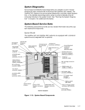
...about the system board and components. The OptiPlex GX1 and OptiPlex NX1 systems are available to the system board. The OptiPlex NX1 systems use server-based diagnostics, hard-disk-based diagnostics, or the diskette-based diagnostics using an external diskette-drive kit connected directly to aid in troubleshooting...DIMM sockets (3) (DIMM_A-DIMM_C) main power input connector (POWER_1) 3.3-V power input connector (POWER_2) system board jumpers primary EIDE diskette/tape drive interface connector interface connector (IDE1) (DSKT) front of the three Dell OptiPlex GX1 chassis.
...about the system board and components. The OptiPlex GX1 and OptiPlex NX1 systems are available to the system board. The OptiPlex NX1 systems use server-based diagnostics, hard-disk-based diagnostics, or the diskette-based diagnostics using an external diskette-drive kit connected directly to aid in troubleshooting...DIMM sockets (3) (DIMM_A-DIMM_C) main power input connector (POWER_1) 3.3-V power input connector (POWER_2) system board jumpers primary EIDE diskette/tape drive interface connector interface connector (IDE1) (DSKT) front of the three Dell OptiPlex GX1 chassis.

Service Manual
Page 32
... super I/O controller to initiate DMA cycle for use by RTC alarm event. The following subsections provide service-related information about hard-disk drive options for use by device connected to primary EIDE port to indicate that device requires service. IRQ14 Generated by an expansion... card. IRQ11* NIC/default PCI IRQ. IRQ10 Available for attached diskette drive DREQ3 Available DREQ4 Generated by keyboard controller to indicate that mouse's output buffer is full. IRQ8 Generated by an expansion card....
... super I/O controller to initiate DMA cycle for use by RTC alarm event. The following subsections provide service-related information about hard-disk drive options for use by device connected to primary EIDE port to indicate that device requires service. IRQ14 Generated by an expansion... card. IRQ11* NIC/default PCI IRQ. IRQ10 Available for attached diskette drive DREQ3 Available DREQ4 Generated by keyboard controller to indicate that mouse's output buffer is full. IRQ8 Generated by an expansion card....

Service Manual
Page 33
... Tower Chassis front Midsize Chassis The hard-disk drive assembly (consisting of the hard-disk drive and the harddisk drive bracket) is attached to the bottom of the computer. back back left side left right side side right side front Low-Profile Chassis top back front OptiPlex NX1 Chassis back left front of... the computer and is located inside the chassis at the front of the chassis. One 1-inch-high EIDE or SCSI hard-disk drive can contain either one or two 1-inch-high EIDE or...
... Tower Chassis front Midsize Chassis The hard-disk drive assembly (consisting of the hard-disk drive and the harddisk drive bracket) is attached to the bottom of the computer. back back left side left right side side right side front Low-Profile Chassis top back front OptiPlex NX1 Chassis back left front of... the computer and is located inside the chassis at the front of the chassis. One 1-inch-high EIDE or SCSI hard-disk drive can contain either one or two 1-inch-high EIDE or...

Service Manual
Page 34
...contain either one or two 1-inch-high EIDE or SCSI hard-disk drives, or one 1-inch-high EIDE or SCSI hard-disk drive and one 1.6-inch-high EIDE or SCSI hard-disk drive. The hard-disk drive bracket is located beneath the externally accessible drive bays at 50 to 60 Hz. Therefore, when you...condition. The system power supply provides the DC operating voltages and currents listed in Table 1-4. The hard-disk drive bracket can be connected to their corresponding power input connectors on the system board or drives. +3.3 VDC +3.15 to +3.45 VDC 12.0 A1 (low-profile computers); 14.0 A1 ...
...contain either one or two 1-inch-high EIDE or SCSI hard-disk drives, or one 1-inch-high EIDE or SCSI hard-disk drive and one 1.6-inch-high EIDE or SCSI hard-disk drive. The hard-disk drive bracket is located beneath the externally accessible drive bays at 50 to 60 Hz. Therefore, when you...condition. The system power supply provides the DC operating voltages and currents listed in Table 1-4. The hard-disk drive bracket can be connected to their corresponding power input connectors on the system board or drives. +3.3 VDC +3.15 to +3.45 VDC 12.0 A1 (low-profile computers); 14.0 A1 ...
Service Manual
Page 36
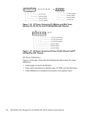
1234 P2, P3, P5, P6, P9 +5 VDC (red) common (black) common (black) +12 VDC (yellow) P4 12 34 +12 VDC (yellow) common (black) common (black) +5 VDC (red) P2, P7 1 2 34 5 6 +3.3 VDC (blue/white) +3.3 VDC (blue/white) +3.3 VDC (blue/white) common (black) common (black) common (black) Figures 1-18 through 1-22 provide the following information about DC power distribution: Power-supply connector identification Power cable connections for diskette, tape, CD-ROM, and hard-disk drives Power distribution to sockets and connectors on the system board 1-24
1234 P2, P3, P5, P6, P9 +5 VDC (red) common (black) common (black) +12 VDC (yellow) P4 12 34 +12 VDC (yellow) common (black) common (black) +5 VDC (red) P2, P7 1 2 34 5 6 +3.3 VDC (blue/white) +3.3 VDC (blue/white) +3.3 VDC (blue/white) common (black) common (black) common (black) Figures 1-18 through 1-22 provide the following information about DC power distribution: Power-supply connector identification Power cable connections for diskette, tape, CD-ROM, and hard-disk drives Power distribution to sockets and connectors on the system board 1-24

Service Manual
Page 40
... VDC +5 VFP +5 VDC -5 VDC +12 VDC -12 VDC PCI1 through PCI3 P1 ISA1 through ISA3 +12 VDC FAN internal P2 hard-disk drive internal P3 hard-disk drive P4 3.5-inch diskette drive P5* optional drive P6* optional drive main memory DIMM_A DIMM_B DIMM_C +5 VFP +5 VDC +5 VDC +5 VDC +5 VDC MICROPROCESSOR processor core regulator +3.3 VDC core VCC +2.1 to +3.5 VDC...
... VDC +5 VFP +5 VDC -5 VDC +12 VDC -12 VDC PCI1 through PCI3 P1 ISA1 through ISA3 +12 VDC FAN internal P2 hard-disk drive internal P3 hard-disk drive P4 3.5-inch diskette drive P5* optional drive P6* optional drive main memory DIMM_A DIMM_B DIMM_C +5 VFP +5 VDC +5 VDC +5 VDC +5 VDC MICROPROCESSOR processor core regulator +3.3 VDC core VCC +2.1 to +3.5 VDC...

Service Manual
Page 58
...above the Hard Drive C: category in this chapter. When an error is encountered. If you wait more than 3 seconds before pressing the , the message disappears and the load operation continues. The tests continue to cancel. The OptiPlex NX1 systems use either server-based, hard-disk-based,... or (optionally) diskette-based diagnostics using an external diskette-drive kit connected to reboot the system. To run until an error is reported...
...above the Hard Drive C: category in this chapter. When an error is encountered. If you wait more than 3 seconds before pressing the , the message disappears and the load operation continues. The tests continue to cancel. The OptiPlex NX1 systems use either server-based, hard-disk-based,... or (optionally) diskette-based diagnostics using an external diskette-drive kit connected to reboot the system. To run until an error is reported...

Service Manual
Page 169
... in your system: Boot Device Priority Exclude From Boot Device Priority Device Controller Priority The Boot Device Priority category lists all bootable devices (hard-disk drives, CD-ROM drives, and so on) that are controlled by the system BIOS and any Plug and Play network adapters installed in the Boot Device Priority... category. When determining the order of the devices, press and the up into the Exclude From Boot Device Priority category. NOTE: The system defines Hard Drive C: in the Boot Device Priority category as the first hard-disk drive attached to ignore during system start -up -
... in your system: Boot Device Priority Exclude From Boot Device Priority Device Controller Priority The Boot Device Priority category lists all bootable devices (hard-disk drives, CD-ROM drives, and so on) that are controlled by the system BIOS and any Plug and Play network adapters installed in the Boot Device Priority... category. When determining the order of the devices, press and the up into the Exclude From Boot Device Priority category. NOTE: The system defines Hard Drive C: in the Boot Device Priority category as the first hard-disk drive attached to ignore during system start -up -


