Service Manual
Page 10
... audio controller. • PCI video card. • Integrated 10-Mbps or 10/100-Mbps Ethernet NIC. • Integrated Universal Serial Bus (USB) controller with the Intel 82440FX PCIset. • SMART support-compliant hard-disk drives and SMART support in the system BIOS, which warns you at system start-up if a hard-disk drive has become unreliable. • Quick tests feature in the diskette-based diagnostics (for more information about Run Quick Tests, see "Running...
... audio controller. • PCI video card. • Integrated 10-Mbps or 10/100-Mbps Ethernet NIC. • Integrated Universal Serial Bus (USB) controller with the Intel 82440FX PCIset. • SMART support-compliant hard-disk drives and SMART support in the system BIOS, which warns you at system start-up if a hard-disk drive has become unreliable. • Quick tests feature in the diskette-based diagnostics (for more information about Run Quick Tests, see "Running...
Service Manual
Page 12
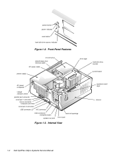
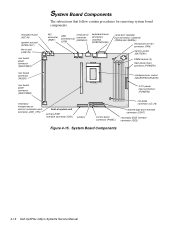
power button power indicator reset button hard-disk drive access indicator Figure 1-2. Internal View expansion-card cage chassis 1-4 Dell OptiPlex GXpro Systems Service Manual Front-Panel Features 3.5-inch drive diskette/tape drive interface cable DC power cable power supply drive cage hard-disk drive bracket system board AC power receptacle voltage selection switch parallel port connector serial port 1 connector mouse connector keyboard connector serial port 2 connector USB connector (2) NIC connector video connector microphone jack speaker-out jack card-slot openings line-in jack ...
power button power indicator reset button hard-disk drive access indicator Figure 1-2. Internal View expansion-card cage chassis 1-4 Dell OptiPlex GXpro Systems Service Manual Front-Panel Features 3.5-inch drive diskette/tape drive interface cable DC power cable power supply drive cage hard-disk drive bracket system board AC power receptacle voltage selection switch parallel port connector serial port 1 connector mouse connector keyboard connector serial port 2 connector USB connector (2) NIC connector video connector microphone jack speaker-out jack card-slot openings line-in jack ...
Service Manual
Page 14
...-in the User's Guide provides instructions for connecting the system to external audio devices and configuring the integrated audio controller to two high-performance EIDE devices, typically EIDE tape drives or CD-ROM drives. NOTE: Some users may use an ISA video adapter card. 1-6 Dell OptiPlex GXpro Systems Service Manual The EIDE controller resides on the high-speed PCI local bus. • The primary EIDE interface (IDE1) provides support for up to two EIDE devices. NOTE: The externally accessible drive bays...
...-in the User's Guide provides instructions for connecting the system to external audio devices and configuring the integrated audio controller to two high-performance EIDE devices, typically EIDE tape drives or CD-ROM drives. NOTE: Some users may use an ISA video adapter card. 1-6 Dell OptiPlex GXpro Systems Service Manual The EIDE controller resides on the high-speed PCI local bus. • The primary EIDE interface (IDE1) provides support for up to two EIDE devices. NOTE: The externally accessible drive bays...
Service Manual
Page 15
... the User's Guide provides instructions for connecting the system to the NIC connector on the computer's back panel • The message USB Enhanced displayed during the boot routine • A USB category on systems with the 10/100-Mbps NIC. Thermal Monitoring The primary and, if installed, secondary microprocessors have a thermal sensor that the system will shut down in the 100-Mbps mode, a category-5 ethernet cable...
... the User's Guide provides instructions for connecting the system to the NIC connector on the computer's back panel • The message USB Enhanced displayed during the boot routine • A USB category on systems with the 10/100-Mbps NIC. Thermal Monitoring The primary and, if installed, secondary microprocessors have a thermal sensor that the system will shut down in the 100-Mbps mode, a category-5 ethernet cable...
Service Manual
Page 20
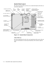
...(NIC-IN) speaker-out jack (SPKR-OUT) line-in jack (LINE-IN) riser board power connector (RSR PWR1) System Board Layout The subsections that came with your system for information on removing and replacing video-memory upgrade chips. 1-12 Dell OptiPlex GXpro Systems Service Manual NIC connector (ENET) USB connector (USB) serial port 2 connector (SERIAL2) keyboard/mouse connectors (stacked) (KYBD/MOUSE) serial port 1/parallel port connectors (stacked) (PARALLEL/SERIAL) microprocessor fan connector (FAN) battery socket (BATTERY) DIMM sockets (4) main power input connector (POWER1) riser...
...(NIC-IN) speaker-out jack (SPKR-OUT) line-in jack (LINE-IN) riser board power connector (RSR PWR1) System Board Layout The subsections that came with your system for information on removing and replacing video-memory upgrade chips. 1-12 Dell OptiPlex GXpro Systems Service Manual NIC connector (ENET) USB connector (USB) serial port 2 connector (SERIAL2) keyboard/mouse connectors (stacked) (KYBD/MOUSE) serial port 1/parallel port connectors (stacked) (PARALLEL/SERIAL) microprocessor fan connector (FAN) battery socket (BATTERY) DIMM sockets (4) main power input connector (POWER1) riser...
Service Manual
Page 22
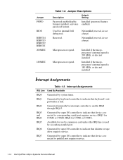
... I/O controller to indicate that device connected to parallel port requires service. 1-14 Dell OptiPlex GXpro Systems Service Manual Installed (password feature Jumper installed, activates enabled) password feature. Used for COM1 or COM3). Jumper PSWD BIOS RSRVD4 RSRVD3 RSRVD2 RSRVD1 200MHZ 180MHZ Table 1-2. IRQ4 for internal Dell debug tool. IRQ5 Available for COM2 or COM4; IRQ3 and IRQ4 Generated by super I /O controller to indicate that device connected to corresponding serial port requires service (IRQ3 for use by expansion card...
... I/O controller to indicate that device connected to parallel port requires service. 1-14 Dell OptiPlex GXpro Systems Service Manual Installed (password feature Jumper installed, activates enabled) password feature. Used for COM1 or COM3). Jumper PSWD BIOS RSRVD4 RSRVD3 RSRVD2 RSRVD1 200MHZ 180MHZ Table 1-2. IRQ4 for internal Dell debug tool. IRQ5 Available for COM2 or COM4; IRQ3 and IRQ4 Generated by super I /O controller to indicate that device connected to corresponding serial port requires service (IRQ3 for use by expansion card...
Service Manual
Page 25
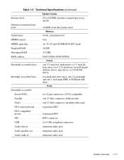
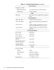
...-ROM drives Internally accessible bays . . . . two hard-disk drive bays; one 1.6-inch-high and one 1-inch-high EIDE or SCSI hard-disk drive Ports Externally accessible: Serial (DTE two 9-pin connectors; 16550-compatible Parallel one 25-hole connector (bidirectional) Video one 3.5-inch bay, dedicated to a 3.5-inch diskette drive; one 15-hole connector (on add-in video card) PS/2-style keyboard . . . . . 6-pin mini-DIN PS/2-compatible mouse 6-pin mini-DIN NIC RJ45 connector USB two USB-compliant connectors Audio line in miniature audio jack Audio speaker...
...-ROM drives Internally accessible bays . . . . two hard-disk drive bays; one 1.6-inch-high and one 1-inch-high EIDE or SCSI hard-disk drive Ports Externally accessible: Serial (DTE two 9-pin connectors; 16550-compatible Parallel one 25-hole connector (bidirectional) Video one 3.5-inch bay, dedicated to a 3.5-inch diskette drive; one 15-hole connector (on add-in video card) PS/2-style keyboard . . . . . 6-pin mini-DIN PS/2-compatible mouse 6-pin mini-DIN NIC RJ45 connector USB two USB-compliant connectors Audio line in miniature audio jack Audio speaker...
Service Manual
Page 26
two 40-pin connectors on PCI local bus Diskette drive 34-pin connector Video Video type PCI video card (see manufacturer's specifications) Key Combinations Table 1-5. Technical Specifications (continued) Ports (continued) Internally accessible: EIDE hard-disk drive . . . .
two 40-pin connectors on PCI local bus Diskette drive 34-pin connector Video Video type PCI video card (see manufacturer's specifications) Key Combinations Table 1-5. Technical Specifications (continued) Ports (continued) Internally accessible: EIDE hard-disk drive . . . .
Service Manual
Page 29
... appropriate user documentation for troubleshooting the system. After the user describes the problem, follow these steps: 1. Yes. Instruct the user in the proper procedure, or direct him or her to use. Basic Troubleshooting 2-1 Appendix D, "Maintaining the System," in the User's Guide provides information about backing up any data on the hard-disk drive if the system's condition permits. Observe the user to step 3. Dell recommends...
... appropriate user documentation for troubleshooting the system. After the user describes the problem, follow these steps: 1. Yes. Instruct the user in the proper procedure, or direct him or her to use. Basic Troubleshooting 2-1 Appendix D, "Maintaining the System," in the User's Guide provides information about backing up any data on the hard-disk drive if the system's condition permits. Observe the user to step 3. Dell recommends...
Service Manual
Page 30
... peripherals, and cables. For a PS/2-compatible mouse, the keyboard and mouse interface cable connectors are sticking, it may be necessary to replace the keyboard. 2-2 Dell OptiPlex GXpro Systems Service Manual Verify that all power cables are properly connected to the serial ports, parallel port, and USB are properly attached. Each of the serial, parallel, and USB interface cables must be firmly attached to an appropriate connector on the device. For proper settings of the video monitor controls, see...
... peripherals, and cables. For a PS/2-compatible mouse, the keyboard and mouse interface cable connectors are sticking, it may be necessary to replace the keyboard. 2-2 Dell OptiPlex GXpro Systems Service Manual Verify that all power cables are properly connected to the serial ports, parallel port, and USB are properly attached. Each of the serial, parallel, and USB interface cables must be firmly attached to an appropriate connector on the device. For proper settings of the video monitor controls, see...
Service Manual
Page 31
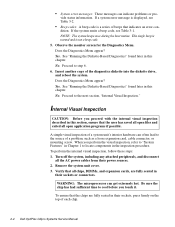
... Chapter 4, "Removing and Replacing Parts." To observe problem indications during the boot routine, troubleshoot the diskette drive or hard-disk drive subsystem, as described in the previous section, you have performed an external visual inspection as appropriate. Insert the diagnostics diskette into drive A. Does the fan run normally? Yes. Proceed to the next section, "Observing the Boot Routine." Basic Troubleshooting 2-3 8. Yes. Proceed to step 4. Check the power supply fan. Watch...
... Chapter 4, "Removing and Replacing Parts." To observe problem indications during the boot routine, troubleshoot the diskette drive or hard-disk drive subsystem, as described in the previous section, you have performed an external visual inspection as appropriate. Insert the diagnostics diskette into drive A. Does the fan run normally? Yes. Proceed to the next section, "Observing the Boot Routine." Basic Troubleshooting 2-3 8. Yes. Proceed to step 4. Check the power supply fan. Watch...
Service Manual
Page 32
...'s interior hardware can get extremely hot. A simple visual inspection of each chip. 2-4 Dell OptiPlex GXpro Systems Service Manual Turn off the system, including any attached peripherals, and disconnect all chips, DIMMs, and expansion cards, are fully seated in this chapter. NOTE: The system beeps once during the boot routine. Observe the monitor screen for the Diagnostics Menu. This single beep is normal and is displayed...
...'s interior hardware can get extremely hot. A simple visual inspection of each chip. 2-4 Dell OptiPlex GXpro Systems Service Manual Turn off the system, including any attached peripherals, and disconnect all chips, DIMMs, and expansion cards, are fully seated in this chapter. NOTE: The system beeps once during the boot routine. Observe the monitor screen for the Diagnostics Menu. This single beep is normal and is displayed...
Service Manual
Page 35
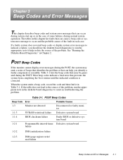
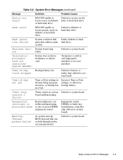
... register write/ read failure Beep Codes and Error Messages 3-1 POST Beep Codes If the monitor cannot display error messages during the POST, the system may be generated during the POST. Table 3-1 lists the beep codes that prevents the system from completing the boot routine until the indicated condition is corrected. Most beep codes indicate a fatal error that may emit a series of beeps that identifies the problem or that can...
... register write/ read failure Beep Codes and Error Messages 3-1 POST Beep Codes If the monitor cannot display error messages during the POST, the system may be generated during the POST. Table 3-1 lists the beep codes that prevents the system from completing the boot routine until the indicated condition is corrected. Most beep codes indicate a fatal error that may emit a series of beeps that identifies the problem or that can...
Service Manual
Page 37
... line failure • Keyboard controller failure • Keyboard data line failure • Keyboard stuck key failure • No timer tick interrupt • Shutdown failure • Terminator/processor card not installed! When a fatal error occurs, the system usually cannot be rebooted until an appropriate hardware change has been made. POST Beep Codes (continued) Beep Code Error Probable Causes 4-3-3 Timer-chip counter 2 failure Defective system board 4-3-4 Time-of-day clock stopped Bad battery or defective system board 4-4-1 Serial/parallel port test failure...
... line failure • Keyboard controller failure • Keyboard data line failure • Keyboard stuck key failure • No timer tick interrupt • Shutdown failure • Terminator/processor card not installed! When a fatal error occurs, the system usually cannot be rebooted until an appropriate hardware change has been made. POST Beep Codes (continued) Beep Code Error Probable Causes 4-3-3 Timer-chip counter 2 failure Defective system board 4-3-4 Time-of-day clock stopped Bad battery or defective system board 4-4-1 Serial/parallel port test failure...
Service Manual
Page 39
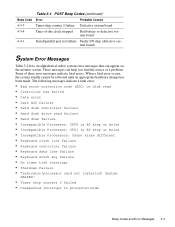
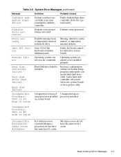
... keyboard controller (defective system board). Diskette write-protected. Microprocessors do not have the same level-2 cache. Diskette write protected Diskette write-protect feature activated. Drive not ready Diskette missing from or improperly inserted in System Setup program, improperly connected hard-disk drive cable, faulty hard-disk controller subsystem (defective system board), or loose power cable. Table 3-2. Faulty diskette/tape drive controller (defective system board). Hard disk controller failure Hard disk drive read failure Hard disk failure Hard-disk drive...
... keyboard controller (defective system board). Diskette write-protected. Microprocessors do not have the same level-2 cache. Diskette write protected Diskette write-protect feature activated. Drive not ready Diskette missing from or improperly inserted in System Setup program, improperly connected hard-disk drive cable, faulty hard-disk controller subsystem (defective system board), or loose power cable. Table 3-2. Faulty diskette/tape drive controller (defective system board). Hard disk controller failure Hard disk drive read failure Hard disk failure Hard-disk drive...
Service Manual
Page 43
... system board). or hard-disk drive. Time-of -day not set Time or Date settings in protected mode Keyboard/mouse controller malfunctioning, or one or both thermal probes are nonoperational. Defective system board. Beep Codes and Error Messages 3-9 Table 3-2. Terminator/ processor card not installed! System does not have terminator or add-in card improperly installed, or no card installed. clock stopped Defective battery or faulty chip (defective system board). Unexpected interrupt in System Setup program...
... system board). or hard-disk drive. Time-of -day not set Time or Date settings in protected mode Keyboard/mouse controller malfunctioning, or one or both thermal probes are nonoperational. Defective system board. Beep Codes and Error Messages 3-9 Table 3-2. Terminator/ processor card not installed! System does not have terminator or add-in card improperly installed, or no card installed. clock stopped Defective battery or faulty chip (defective system board). Unexpected interrupt in System Setup program...
Service Manual
Page 60
... board power connector (RSR PWR2) NIC connector (ENET) USB connectors(2) (USB) serial port 2 connector (SERIAL2) keyboard/mouse connectors (stacked) (KYBD/MOUSE) serial port 1/parallel port connectors (stacked) (PARALLEL/SERIAL) microprocessor fan connector (FAN) battery socket (BATTERY) DIMM sockets (4) main power input connector (POWER1) microprocessor socket (MICROPROCESSOR) 3.3-V power input connectors (POWER2) secondary microprocessor card (or terminator card) connector (2ND_CPU) front of system unit primary EIDE interface connector (IDE1) jumpers control panel connector (PANEL...
... board power connector (RSR PWR2) NIC connector (ENET) USB connectors(2) (USB) serial port 2 connector (SERIAL2) keyboard/mouse connectors (stacked) (KYBD/MOUSE) serial port 1/parallel port connectors (stacked) (PARALLEL/SERIAL) microprocessor fan connector (FAN) battery socket (BATTERY) DIMM sockets (4) main power input connector (POWER1) microprocessor socket (MICROPROCESSOR) 3.3-V power input connectors (POWER2) secondary microprocessor card (or terminator card) connector (2ND_CPU) front of system unit primary EIDE interface connector (IDE1) jumpers control panel connector (PANEL...
Service Manual
Page 72
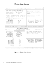
... a field, enter a number or use the leftor right-arrow key. System Setup Screens Page 1 of 2 Dell Computer Corporation System OptiPlex GXpro 200 Setup BIOS Version: XXX Keyboard Errors: Report System Password: Not Enabled Password Status: Unlocked Boot Sequence: Diskette First Setup Password: Not Enabled Auto Power On: Mon-Fri 07:30 Power Management: Regular Integrated Devices Sound: On NIC: On Mouse: On Serial Port 1: Auto Serial Port 2: Auto Parallel Port: 378h Parallel Mode: AT IDE Hard Disk: Auto Diskette: Auto USB: On Speakers: On This...
... a field, enter a number or use the leftor right-arrow key. System Setup Screens Page 1 of 2 Dell Computer Corporation System OptiPlex GXpro 200 Setup BIOS Version: XXX Keyboard Errors: Report System Password: Not Enabled Password Status: Unlocked Boot Sequence: Diskette First Setup Password: Not Enabled Auto Power On: Mon-Fri 07:30 Power Management: Regular Integrated Devices Sound: On NIC: On Mouse: On Serial Port 1: Auto Serial Port 2: Auto Parallel Port: 378h Parallel Mode: AT IDE Hard Disk: Auto Diskette: Auto USB: On Speakers: On This...
Service Manual
Page 77
..., 1-15 drive cage, 1-4, 4-10 drive hardware, 4-9 Index 1 Index Numbers 3.3-V power input connectors, 1-12, 4-16 A AC power receptacle, 1-4 add-in card, removal, 4-24 audio controller, 1-6 CD-ROM connector, 1-12 drives, 4-11 chassis, 1-4 computer, technical specifications, 1-16 configuration jumpers, location, 1-12, 4-16 connectors location on back of system unit, 1-4 location on system board, 1-12, 4-16 cover, system unit, removal, 4-4 B battery illustrated, 4-25 removing and replacing, 4-25 socket, 1-12, 4-16 beep codes, 3-1 BIOS chip, 1-12, 4-16 boot routine, observing when trouble-
..., 1-15 drive cage, 1-4, 4-10 drive hardware, 4-9 Index 1 Index Numbers 3.3-V power input connectors, 1-12, 4-16 A AC power receptacle, 1-4 add-in card, removal, 4-24 audio controller, 1-6 CD-ROM connector, 1-12 drives, 4-11 chassis, 1-4 computer, technical specifications, 1-16 configuration jumpers, location, 1-12, 4-16 connectors location on back of system unit, 1-4 location on system board, 1-12, 4-16 cover, system unit, removal, 4-4 B battery illustrated, 4-25 removing and replacing, 4-25 socket, 1-12, 4-16 beep codes, 3-1 BIOS chip, 1-12, 4-16 boot routine, observing when trouble-
Service Manual
Page 79
... power indicator, 1-4 power input connectors, 1-12, 4-16 power supply, 1-8 cable configuration, 1-10 DC voltage ranges, 1-8 illustrated, 1-10 removal, 4-14 precautions, 4-2 R reset button location, 1-4 removal, 4-5 resource conflicts eliminating, 2-5 riser board connector, 1-12 power connector, 1-12 removal, 4-19 P padlock, 4-4 PANEL connector, 4-16 Panel connector, 1-12 parallel port connector location, 1-4, 1-12, 4-16 PCI expansion cards, 1-5, 1-12, 4-16, 4-17, 4-18 PCI video card, 1-6 S secondary microprocessor, 4-23 serial port connectors, location, 1-4 SMART support, 1-8 sockets battery...
... power indicator, 1-4 power input connectors, 1-12, 4-16 power supply, 1-8 cable configuration, 1-10 DC voltage ranges, 1-8 illustrated, 1-10 removal, 4-14 precautions, 4-2 R reset button location, 1-4 removal, 4-5 resource conflicts eliminating, 2-5 riser board connector, 1-12 power connector, 1-12 removal, 4-19 P padlock, 4-4 PANEL connector, 4-16 Panel connector, 1-12 parallel port connector location, 1-4, 1-12, 4-16 PCI expansion cards, 1-5, 1-12, 4-16, 4-17, 4-18 PCI video card, 1-6 S secondary microprocessor, 4-23 serial port connectors, location, 1-4 SMART support, 1-8 sockets battery...


