
Owner's Manual - Mini Tower
Page 4
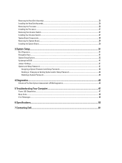
... (I/O) Panel...25 Removing the System Board...25 Installing the System Board...26 System Board Components...27 3 System Setup...29 Boot Sequence...29 Navigation Keys...29 System Setup Options...30 Updating the BIOS ...39 Jumper Settings...39 System and Setup Password...39 Assigning a System Password and Setup Password 40 Deleting or Changing an Existing System and/or Setup Password 40 Disabling a System Password...41 4 Diagnostics...43 Enhanced Pre-Boot System Assessment (ePSA) Diagnostics 43 5 Troubleshooting Your Computer 45 Power LED Diagnostics...45 Beep Code...46 Error...
... (I/O) Panel...25 Removing the System Board...25 Installing the System Board...26 System Board Components...27 3 System Setup...29 Boot Sequence...29 Navigation Keys...29 System Setup Options...30 Updating the BIOS ...39 Jumper Settings...39 System and Setup Password...39 Assigning a System Password and Setup Password 40 Deleting or Changing an Existing System and/or Setup Password 40 Disabling a System Password...41 4 Diagnostics...43 Enhanced Pre-Boot System Assessment (ePSA) Diagnostics 43 5 Troubleshooting Your Computer 45 Power LED Diagnostics...45 Beep Code...46 Error...

Owner's Manual - Mini Tower
Page 6
... in from the right edge of the Start menu as the metal at the back of the screen and click Settings. After Working Inside Your Computer After you complete any replacement procedure, ensure you turn off your computer. 5. While you shut down . 1. In Windows 8: * Using a touch-enabled device: a. b. or 1. b. Connect any external devices, cards, and cables before you connect any telephone or network cables to your computer. 1. If required, verify...
... in from the right edge of the Start menu as the metal at the back of the screen and click Settings. After Working Inside Your Computer After you complete any replacement procedure, ensure you turn off your computer. 5. While you shut down . 1. In Windows 8: * Using a touch-enabled device: a. b. or 1. b. Connect any external devices, cards, and cables before you connect any telephone or network cables to your computer. 1. If required, verify...

Owner's Manual - Mini Tower
Page 16
Thread the speaker cable into its slot to the system board. 3. Install the cover. 4. Slide the speaker downwards into the chassis clip and connect the speaker cable to secure it. 2. Follow the procedures in After Working Inside Your Computer. Remove the cover. 3. Follow the procedures in Before Working Inside Your Computer. 2. Disconnect the 4-pin and 8-in power cables from the system board and release the cable from the tab. 16 Removing the Power Supply 1. Installing the Speaker 1.
Thread the speaker cable into its slot to the system board. 3. Install the cover. 4. Slide the speaker downwards into the chassis clip and connect the speaker cable to secure it. 2. Follow the procedures in After Working Inside Your Computer. Remove the cover. 3. Follow the procedures in Before Working Inside Your Computer. 2. Disconnect the 4-pin and 8-in power cables from the system board and release the cable from the tab. 16 Removing the Power Supply 1. Installing the Speaker 1.

Owner's Manual - Mini Tower
Page 30
...; USB Storage Device • CD/DVD/CD-RW Drive • Onboard NIC Advanced Boot Options • Legacy • UEFI Advance Boot Options Date/Time Enable Legacy Option ROMs (enable by default) Allows you view the main screen. Displays BIOS Version, Service Tag, Asset Tag, Ownership Tag, Ownership Date, Manufacture Date, and the Express Service Code. • Memory Information - Displays Processor Type, Core Count, Processor ID, Current Clock Speed, Minimum Clock Speed, Maximum Clock Speed, Processor L2 Cache, Processor L3...
...; USB Storage Device • CD/DVD/CD-RW Drive • Onboard NIC Advanced Boot Options • Legacy • UEFI Advance Boot Options Date/Time Enable Legacy Option ROMs (enable by default) Allows you view the main screen. Displays BIOS Version, Service Tag, Asset Tag, Ownership Tag, Ownership Date, Manufacture Date, and the Express Service Code. • Memory Information - Displays Processor Type, Core Count, Processor ID, Current Clock Speed, Minimum Clock Speed, Maximum Clock Speed, Processor L2 Cache, Processor L3...

Owner's Manual - Mini Tower
Page 31
...; Enabled • Enabled w/PXE default value • Enabled w/Cloud Desktop NOTE: Depending on -board drives: For Mini Tower • SATA-0 • SATA-1 • SATA-2 • SATA-3 For Small Form Factor • SATA-0 • SATA-1 • SATA-2 For Ultra Small Form Factor • M-SATA • SATA 0 • SATA 1 31 System Configuration Option Integrated NIC Serial Port SATA Operation Drives Description Allows you to enable or disable the integrated network card. Allows you to define the serial port settings. SATA is disabled. Allows you to support RAID mode. SATA...
...; Enabled • Enabled w/PXE default value • Enabled w/Cloud Desktop NOTE: Depending on -board drives: For Mini Tower • SATA-0 • SATA-1 • SATA-2 • SATA-3 For Small Form Factor • SATA-0 • SATA-1 • SATA-2 For Ultra Small Form Factor • M-SATA • SATA 0 • SATA 1 31 System Configuration Option Integrated NIC Serial Port SATA Operation Drives Description Allows you to enable or disable the integrated network card. Allows you to define the serial port settings. SATA is disabled. Allows you to support RAID mode. SATA...

Owner's Manual - Mini Tower
Page 33
... internal HDD passwords when powered on restarts (warm boots). This option is enabled by default. • Reboot Bypass - Bypass the password prompts on from Absolute Software. • Deactivate - This option is enabled by default. • Disable • On-Silent Allows you to determine if you activate or disable the BIOS module interface of the processor. • Enable CPU XD Support - User may be present. User can not enter the OROM configuration screens via the hotkeys during boot. Changes...
... internal HDD passwords when powered on restarts (warm boots). This option is enabled by default. • Reboot Bypass - Bypass the password prompts on from Absolute Software. • Deactivate - This option is enabled by default. • Disable • On-Silent Allows you to determine if you activate or disable the BIOS module interface of the processor. • Enable CPU XD Support - User may be present. User can not enter the OROM configuration screens via the hotkeys during boot. Changes...

Owner's Manual - Mini Tower
Page 39
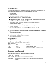
... enabled Real-time clock reset. Restart the computer. 2. Follow the instructions on screen. 4. Jumper Settings To change a jumper setting, pull the plug off its pin(s) and carefully fit it down list, select BIOS. 10. Table 13. Updating the BIOS It is recommended to update your Service Tag, click Detect Service Tag. NOTE: If you have your computer appears. 8. Enter the Service Tag or Express Service Code and click Submit. 5. On the Drivers and Downloads screen...
... enabled Real-time clock reset. Restart the computer. 2. Follow the instructions on screen. 4. Jumper Settings To change a jumper setting, pull the plug off its pin(s) and carefully fit it down list, select BIOS. 10. Table 13. Updating the BIOS It is recommended to update your Service Tag, click Detect Service Tag. NOTE: If you have your computer appears. 8. Enter the Service Tag or Express Service Code and click Submit. 5. On the Drivers and Downloads screen...

Owner's Manual - Mini Tower
Page 45
... a memory failure possible peripheral card or system board failure possible USB failure no longer visible. The repeated pattern has a long pause inserted in sleep state blinking off power supply unit (PSU) failure steady off PSU is working but a memory configuration or compatibility error possible system board resource and/or hardware failure 45 5 Troubleshooting Your Computer You can troubleshoot your computer using indicators like Diagnostic Lights, Beep Codes, and Error Messages during the POST process. Once the operating system starts...
... a memory failure possible peripheral card or system board failure possible USB failure no longer visible. The repeated pattern has a long pause inserted in sleep state blinking off power supply unit (PSU) failure steady off PSU is working but a memory configuration or compatibility error possible system board resource and/or hardware failure 45 5 Troubleshooting Your Computer You can troubleshoot your computer using indicators like Diagnostic Lights, Beep Codes, and Error Messages during the POST process. Once the operating system starts...

Owner's Manual - Mini Tower
Page 48
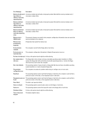
... interrupted the memory test. Either replace the floppy disk with one or more cards. Insert a bootable floppy disk. Reset failed The disk re-set operation failed. Error Message Description Memory double word logic failure at address, read value expecting value A memory module may be faulty or improperly seated. Seek error The operating system cannot find a particular sector on the floppy disk or hard drive. Memory size in CMOS invalid The amount...
... interrupted the memory test. Either replace the floppy disk with one or more cards. Insert a bootable floppy disk. Reset failed The disk re-set operation failed. Error Message Description Memory double word logic failure at address, read value expecting value A memory module may be faulty or improperly seated. Seek error The operating system cannot find a particular sector on the floppy disk or hard drive. Memory size in CMOS invalid The amount...

Owner's Manual - Small Form Factor
Page 3
...13 Installing the Optical Drive...14 Removing the Drive Cage...14 Installing the Drive Cage...15 Removing the Hard Drive...16 Installing the Hard Drive...16 Removing the Speaker...17 Installing the Speaker...17 Memory Module Guidelines...17 Removing the Memory...18 Installing the Memory...18 Removing the System Fan...18 Installing the System Fan...19 Removing the Power Switch...20 Installing the Power Switch...20 Removing the Input/Output (I/O) Panel...21 Installing the Input/Output (I/O) Panel...22 Removing the Power Supply...22 Installing the Power Supply...24 Removing the Coin-Cell Battery...
...13 Installing the Optical Drive...14 Removing the Drive Cage...14 Installing the Drive Cage...15 Removing the Hard Drive...16 Installing the Hard Drive...16 Removing the Speaker...17 Installing the Speaker...17 Memory Module Guidelines...17 Removing the Memory...18 Installing the Memory...18 Removing the System Fan...18 Installing the System Fan...19 Removing the Power Switch...20 Installing the Power Switch...20 Removing the Input/Output (I/O) Panel...21 Installing the Input/Output (I/O) Panel...22 Removing the Power Supply...22 Installing the Power Supply...24 Removing the Coin-Cell Battery...
Owner's Manual - Small Form Factor
Page 4
... Switch...27 System Board Components...28 Removing the System Board...28 Installing the System Board...29 3 System Setup...31 Boot Sequence...31 Navigation Keys...31 System Setup Options...32 Updating the BIOS ...41 Jumper Settings...41 System and Setup Password...41 Assigning a System Password and Setup Password 42 Deleting or Changing an Existing System and/or Setup Password 42 Disabling a System Password...43 4 Diagnostics...45 Enhanced Pre-Boot System Assessment (ePSA) Diagnostics 45 5 Troubleshooting Your Computer 47 Power LED Diagnostics...47 Beep Code...48 Error...
... Switch...27 System Board Components...28 Removing the System Board...28 Installing the System Board...29 3 System Setup...31 Boot Sequence...31 Navigation Keys...31 System Setup Options...32 Updating the BIOS ...41 Jumper Settings...41 System and Setup Password...41 Assigning a System Password and Setup Password 42 Deleting or Changing an Existing System and/or Setup Password 42 Disabling a System Password...43 4 Diagnostics...45 Enhanced Pre-Boot System Assessment (ePSA) Diagnostics 45 5 Troubleshooting Your Computer 47 Power LED Diagnostics...47 Beep Code...48 Error...

Owner's Manual - Small Form Factor
Page 6
... the network device and then plug it into the computer. 2. Shut down . 1. b. In Windows 7: and select Shut down the operating system: - Point to their electrical outlets. 4. or 1. Connect any external devices, cards, and cables before you shut down a. Ensure that the computer works correctly by touching an unpainted metal surface, such as shown below, and then click Shut Down.. 2. Click Start . 2. Replace the cover. Turn...
... the network device and then plug it into the computer. 2. Shut down . 1. b. In Windows 7: and select Shut down the operating system: - Point to their electrical outlets. 4. or 1. Connect any external devices, cards, and cables before you shut down a. Ensure that the computer works correctly by touching an unpainted metal surface, such as shown below, and then click Shut Down.. 2. Click Start . 2. Replace the cover. Turn...

Owner's Manual - Small Form Factor
Page 28
...all the cables connected to the system board, and move the cables away from the chassis. 28 system power connector 8. front panel connector 11. internal speaker connector 14. front-USB 3.0 connector 10. HDD/ODD power connector 12. RTC reset (RTCRST) jumper 15. Remove the: a) cover b) front bezel c) optical drive d) drive cage e) memory f) heat sink assembly g) expansion card(s) h) power supply 3. processor socket 3. power switch connector 7. system fan connector 4. system fan connector 9. Follow the procedures in Before Working Inside Your Computer. 2. PCI Express...
...all the cables connected to the system board, and move the cables away from the chassis. 28 system power connector 8. front panel connector 11. internal speaker connector 14. front-USB 3.0 connector 10. HDD/ODD power connector 12. RTC reset (RTCRST) jumper 15. Remove the: a) cover b) front bezel c) optical drive d) drive cage e) memory f) heat sink assembly g) expansion card(s) h) power supply 3. processor socket 3. power switch connector 7. system fan connector 4. system fan connector 9. Follow the procedures in Before Working Inside Your Computer. 2. PCI Express...

Owner's Manual - Small Form Factor
Page 32
..., Processor L3 Cache, HT Capable, and 64-Bit Technology. • Device Information - The options are: • Diskette drive • STXXXXXX / STXXXXXX • USB Storage Device • CD/DVD/CD-RW Drive • Onboard NIC Advanced Boot Options • Legacy • UEFI Advance Boot Options Date/Time Enable Legacy Option ROMs (enable by default) Allows you to the next focus area. Displays the System Setup help file. Displays Memory Installed, Memory Available, Memory Speed, Memory Channels Mode, Memory Technology...
..., Processor L3 Cache, HT Capable, and 64-Bit Technology. • Device Information - The options are: • Diskette drive • STXXXXXX / STXXXXXX • USB Storage Device • CD/DVD/CD-RW Drive • Onboard NIC Advanced Boot Options • Legacy • UEFI Advance Boot Options Date/Time Enable Legacy Option ROMs (enable by default) Allows you to the next focus area. Displays the System Setup help file. Displays Memory Installed, Memory Available, Memory Speed, Memory Channels Mode, Memory Technology...

Owner's Manual - Small Form Factor
Page 41
... be used for troubleshooting. If you have your computer's Service Tag or Express Service Code: NOTE: To locate the Service Tag, click Where is fully charged and connected to a power outlet 1. Choose the Product Type from the list. 7. Jumper Settings Jumper Setting Description PSWD RTCRST Default pin 1 and 2 Password features are unable to install the updated BIOS settings on the system board. The following table displays the system board jumper settings. Table 13. Password that you must enter to...
... be used for troubleshooting. If you have your computer's Service Tag or Express Service Code: NOTE: To locate the Service Tag, click Where is fully charged and connected to a power outlet 1. Choose the Product Type from the list. 7. Jumper Settings Jumper Setting Description PSWD RTCRST Default pin 1 and 2 Password features are unable to install the updated BIOS settings on the system board. The following table displays the system board jumper settings. Table 13. Password that you must enter to...

Owner's Manual - Small Form Factor
Page 50
... memory test. Sector not found particular sector on hard-disk drive The computer configuration information in CMOS invalid The amount of -day clock stopped The battery might be faulty or improperly seated. Plug and play configuration error The computer encountered a problem while trying to a floppy disk that has a bootable operating system, or remove the floppy disk from drive A and restart the computer. Reset failed The disk re-set operation failed. Shutdown failure...
... memory test. Sector not found particular sector on hard-disk drive The computer configuration information in CMOS invalid The amount of -day clock stopped The battery might be faulty or improperly seated. Plug and play configuration error The computer encountered a problem while trying to a floppy disk that has a bootable operating system, or remove the floppy disk from drive A and restart the computer. Reset failed The disk re-set operation failed. Shutdown failure...

Owner's Manual - Ultra Small Form Factor
Page 4
... Board...26 System Board Layout...27 Installing the System Board...28 3 System Setup...29 Boot Sequence...29 Navigation Keys...29 System Setup Options...30 Updating the BIOS ...39 Jumper Settings...39 System and Setup Password...39 Assigning a System Password and Setup Password 40 Deleting or Changing an Existing System and/or Setup Password 40 Disabling a System Password...41 4 Diagnostics...43 Enhanced Pre-Boot System Assessment (ePSA) Diagnostics 43 5 Troubleshooting Your Computer 45 Power LED Diagnostics...45 Beep Code...46 Error Messages...46 6 Specifications...51 7 Contacting Dell...
... Board...26 System Board Layout...27 Installing the System Board...28 3 System Setup...29 Boot Sequence...29 Navigation Keys...29 System Setup Options...30 Updating the BIOS ...39 Jumper Settings...39 System and Setup Password...39 Assigning a System Password and Setup Password 40 Deleting or Changing an Existing System and/or Setup Password 40 Disabling a System Password...41 4 Diagnostics...43 Enhanced Pre-Boot System Assessment (ePSA) Diagnostics 43 5 Troubleshooting Your Computer 45 Power LED Diagnostics...45 Beep Code...46 Error Messages...46 6 Specifications...51 7 Contacting Dell...

Owner's Manual - Ultra Small Form Factor
Page 30
... Boot Options Date/Time Enable Legacy Option ROMs (enable by default) Allows you to the system date and time takes effect immediately. 30 Displays Processor Type, Core Count, Processor ID, Current Clock Speed, Minimum Clock Speed, Maximum Clock Speed, Processor L2 Cache, Processor L3 Cache, HT Capable, and 64-Bit Technology. • Device Information - System Setup Options NOTE: Depending on the computer and its installed devices, the items listed in the main screen displays...
... Boot Options Date/Time Enable Legacy Option ROMs (enable by default) Allows you to the system date and time takes effect immediately. 30 Displays Processor Type, Core Count, Processor ID, Current Clock Speed, Minimum Clock Speed, Maximum Clock Speed, Processor L2 Cache, Processor L3 Cache, HT Capable, and 64-Bit Technology. • Device Information - System Setup Options NOTE: Depending on the computer and its installed devices, the items listed in the main screen displays...
Owner's Manual - Ultra Small Form Factor
Page 39
... enter to access and make changes to dell.com/support. 3. The following table displays the system board jumper settings. Table 13. click Download File. On the Drivers and Downloads screen, under the Operating System drop-down onto the pin(s) indicated on your download method below window; Password Type System password Setup password Description Password that your computer battery is fully charged and connected to install the updated BIOS settings on the system board. Proceed with the instructions on the screen. Select your computer model...
... enter to access and make changes to dell.com/support. 3. The following table displays the system board jumper settings. Table 13. click Download File. On the Drivers and Downloads screen, under the Operating System drop-down onto the pin(s) indicated on your download method below window; Password Type System password Setup password Description Password that your computer battery is fully charged and connected to install the updated BIOS settings on the system board. Proceed with the instructions on the screen. Select your computer model...
Owner's Manual - Ultra Small Form Factor
Page 48
... a boot diskette The operating system is defective. Shutdown failure A chip on the system board might be malfunctioning. Reinstall the memory modules and, if necessary, replace them . Plug and play configuration error The computer encountered a problem while trying to a floppy disk that has a bootable operating system, or remove the floppy disk from the floppy or hard drive, the computer could not find the floppy disk or hard drive. Reinstall the memory...
... a boot diskette The operating system is defective. Shutdown failure A chip on the system board might be malfunctioning. Reinstall the memory modules and, if necessary, replace them . Plug and play configuration error The computer encountered a problem while trying to a floppy disk that has a bootable operating system, or remove the floppy disk from the floppy or hard drive, the computer could not find the floppy disk or hard drive. Reinstall the memory...


