
User Manual
Page 2
memory card reader Back Panel View 5. microphone connector 7. power supply diagnostic button 2 3. back panel connectors 2. security cable slot 3. line-out connector Back Panel View 1. Back View Figure 2. Back View 1. power supply diagnostic light 2. VESA cover 4. USB 3.0 connectors (2) 6. headphone connector Figure 3. VGA-out connector 4.
memory card reader Back Panel View 5. microphone connector 7. power supply diagnostic button 2 3. back panel connectors 2. security cable slot 3. line-out connector Back Panel View 1. Back View Figure 2. Back View 1. power supply diagnostic light 2. VESA cover 4. USB 3.0 connectors (2) 6. headphone connector Figure 3. VGA-out connector 4.
Owner's Manual
Page 3
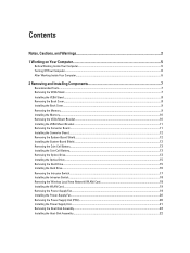
......6 2 Removing and Installing Components 7 Recommended Tools...7 Removing the VESA Stand...7 Installing the VESA Stand...8 Removing the Back Cover...8 Installing the Back Cover...9 Removing the Memory...9 Installing the Memory...10 Removing the VESA Mount Bracket...10 Installing the VESA Mount Bracket...11 Removing the Converter Board...11 Installing the Converter Board...12 Removing...
......6 2 Removing and Installing Components 7 Recommended Tools...7 Removing the VESA Stand...7 Installing the VESA Stand...8 Removing the Back Cover...8 Installing the Back Cover...9 Removing the Memory...9 Installing the Memory...10 Removing the VESA Mount Bracket...10 Installing the VESA Mount Bracket...11 Removing the Converter Board...11 Installing the Converter Board...12 Removing...
Owner's Manual
Page 9
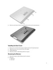
Lift the cover and remove it from the computer using the notches near the input/output panel. Follow the procedures in After Working Inside Your Computer. Installing the Back Cover 1. Follow the procedures in Before Working Inside Your Computer. 2. 4. Remove the: a) VESA stand b) back cover 9 Tighten the screws to secure the back cover to the computer. 3. Install the VESA stand. 4. Place the cover on the back of the computer using the notches near the input/output panel. 2. Removing the Memory 1.
Lift the cover and remove it from the computer using the notches near the input/output panel. Follow the procedures in After Working Inside Your Computer. Installing the Back Cover 1. Follow the procedures in Before Working Inside Your Computer. 2. 4. Remove the: a) VESA stand b) back cover 9 Tighten the screws to secure the back cover to the computer. 3. Install the VESA stand. 4. Place the cover on the back of the computer using the notches near the input/output panel. 2. Removing the Memory 1.
Owner's Manual
Page 10
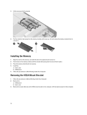
...the: a) VESA stand b) back cover 3. Lift the bracket away from the memory module until the release tabs spring back to the computer. Installing the Memory 1. Align the notch on the memory module until it pops up. Lift the memory shield outwards. 4. Install the: a) back cover b) VESA stand 5. Follow ...the procedures in Before Working Inside Your Computer. 2. Place the memory shield back into its connector. Removing the VESA Mount Bracket 1. 3. Follow the procedures in After Working Inside Your Computer. Remove...
...the: a) VESA stand b) back cover 3. Lift the bracket away from the memory module until the release tabs spring back to the computer. Installing the Memory 1. Align the notch on the memory module until it pops up. Lift the memory shield outwards. 4. Install the: a) back cover b) VESA stand 5. Follow ...the procedures in Before Working Inside Your Computer. 2. Place the memory shield back into its connector. Removing the VESA Mount Bracket 1. 3. Follow the procedures in After Working Inside Your Computer. Remove...

Owner's Manual
Page 29
... the screws to secure the speaker to the system board. 4. Installing the Speakers 1. Remove the: a) VESA stand b) back cover c) VESA mount bracket d) system-board shield e) memory f) optical drive g) hard drive h) heat-sink assembly i) power supply unit j) input/output board shield k) converter board l) power-supply fan 3. Removing the System Board 1. Install: a) system...
... the screws to secure the speaker to the system board. 4. Installing the Speakers 1. Remove the: a) VESA stand b) back cover c) VESA mount bracket d) system-board shield e) memory f) optical drive g) hard drive h) heat-sink assembly i) power supply unit j) input/output board shield k) converter board l) power-supply fan 3. Removing the System Board 1. Install: a) system...

Owner's Manual
Page 30
5. Installing the System Board 1. Place the system board on the computer. 2. Lift and remove the system board from the chassis. Install: a) power-supply fan b) converter board c) input/output board shield d) power supply unit e) heat-sink assembly f) hard drive g) optical drive h) memory i) system-board shield 30 Tighten the screws to secure the system board to the base panel. 3.
5. Installing the System Board 1. Place the system board on the computer. 2. Lift and remove the system board from the chassis. Install: a) power-supply fan b) converter board c) input/output board shield d) power supply unit e) heat-sink assembly f) hard drive g) optical drive h) memory i) system-board shield 30 Tighten the screws to secure the system board to the base panel. 3.

Owner's Manual
Page 38
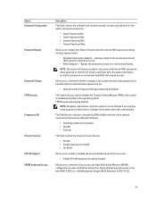
... Device. Boot Sequence This list specifies the order that certain operating systems may not be selected or de-selected from support.dell.com Table 2. NOTE: For the standard graphics browser only. Displays the System Setup help file. The boot devices can also ...be able to use , "Memory Available", is less than "Memory Installed". Expands or collapses a drop‐down list, if applicable. General Option System Information Description Displays the following information: •...
... Device. Boot Sequence This list specifies the order that certain operating systems may not be selected or de-selected from support.dell.com Table 2. NOTE: For the standard graphics browser only. Displays the System Setup help file. The boot devices can also ...be able to use , "Memory Available", is less than "Memory Installed". Expands or collapses a drop‐down list, if applicable. General Option System Information Description Displays the following information: •...

Owner's Manual
Page 39
... the SMART (Self Monitoring Analysis and Reporting Technology) specification. • Enable SMART Reporting - This option configures the operating mode of USB mass storage devices (HDD, memory key, floppy). System Configuration Option Integrated NIC SATA Operation Drives SMART Reporting USB Configuration Description • Onboard NIC • Legacy • UEFI This option controls...
... the SMART (Self Monitoring Analysis and Reporting Technology) specification. • Enable SMART Reporting - This option configures the operating mode of USB mass storage devices (HDD, memory key, floppy). System Configuration Option Integrated NIC SATA Operation Drives SMART Reporting USB Configuration Description • Onboard NIC • Legacy • UEFI This option controls...
Owner's Manual
Page 41
... hard disk passwords are set . • Allow Non-Admin Password Changes (selected by default) Allows you to determine if you access the Option Read Only Memory (OROM) configuration screens via hotkeys during a system restart. • Disabled (selected by default) NOTE: Activation, deactivation, and clear options are not affected if you load...
... hard disk passwords are set . • Allow Non-Admin Password Changes (selected by default) Allows you to determine if you access the Option Read Only Memory (OROM) configuration screens via hotkeys during a system restart. • Disabled (selected by default) NOTE: Activation, deactivation, and clear options are not affected if you load...

Owner's Manual
Page 51
... in an S3 (Sleep state) power state. Gate A20 failure Super I/O chip failure Keyboard controller test failure. 4 RAM Read/Write failure Memory failure 5 RTC Power Fail CMOS battery failure 6 Video BIOS Test Failure Video card failure 7 CPU Failure CPU 51 BIOS System board failure,... covers BIOS corruption or Chip ROM error 2 No RAM Detected Memory failure 3 Chipset Error (North and South Bridge Chipset, System board Failure DMA/IMR/Timer Error for each scenario. Blinking White The ...
... in an S3 (Sleep state) power state. Gate A20 failure Super I/O chip failure Keyboard controller test failure. 4 RAM Read/Write failure Memory failure 5 RTC Power Fail CMOS battery failure 6 Video BIOS Test Failure Video card failure 7 CPU Failure CPU 51 BIOS System board failure,... covers BIOS corruption or Chip ROM error 2 No RAM Detected Memory failure 3 Chipset Error (North and South Bridge Chipset, System board Failure DMA/IMR/Timer Error for each scenario. Blinking White The ...

Owner's Manual
Page 53
... Specification Intel HD2000, HD2500, HD3000 or HD4000 (depends on processor type Intel Q77 Express chipset Table 14. Memory Feature Type Connectors Capacity Minimum Memory Maximum Memory Specification up to 8 MB cache depending on processor selected) shared memory VGA, HDMI, and Wi-Fi display NOTE: Wi-Fi display requires a wireless card which can purchased separately...
... Specification Intel HD2000, HD2500, HD3000 or HD4000 (depends on processor type Intel Q77 Express chipset Table 14. Memory Feature Type Connectors Capacity Minimum Memory Maximum Memory Specification up to 8 MB cache depending on processor selected) shared memory VGA, HDMI, and Wi-Fi display NOTE: Wi-Fi display requires a wireless card which can purchased separately...
Statement of Volatility
Page 1
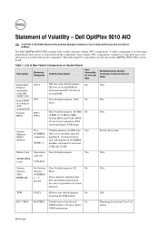
.... RTC CMOS BATTERY Volatile battery back-backed No CMOS memory 256 bytes. The Dell OptiPlex 9010 AIO contains both volatile and non-volatile (NV) components. DDR3 memory Two Volatile memory in 2K bytes of data) Embedded O2U1 96K bytes non-volatile memory. Statement of Non-Volatile Components on -chip RAM. Dell OptiPlex 9010 AIO CAUTION: A CAUTION indicates either potential damage to hardware...
.... RTC CMOS BATTERY Volatile battery back-backed No CMOS memory 256 bytes. The Dell OptiPlex 9010 AIO contains both volatile and non-volatile (NV) components. DDR3 memory Two Volatile memory in 2K bytes of data) Embedded O2U1 96K bytes non-volatile memory. Statement of Non-Volatile Components on -chip RAM. Dell OptiPlex 9010 AIO CAUTION: A CAUTION indicates either potential damage to hardware...
Statement of Volatility
Page 2
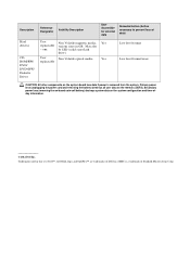
...optical media. be SSD (solid state flash drive). Secondary power loss (removing the on-board coin-cell battery) destroys system data on the memory (DDR3). SMSC is removed from the system. May also - Description Hard drive(s) CDROM/RW/ DVD/ DVD+RW/ Diskette Drives Reference ... (Action necessary to prevent loss of data) User Non Volatile magnetic media, Yes replaceable various sizes in this text: Dell™, the DELL logo, and OptiPlex™ are trademarks of Standard Microsystems Corp. Yes replaceable Low level format Low level format/erase CAUTION: All other components...
...optical media. be SSD (solid state flash drive). Secondary power loss (removing the on-board coin-cell battery) destroys system data on the memory (DDR3). SMSC is removed from the system. May also - Description Hard drive(s) CDROM/RW/ DVD/ DVD+RW/ Diskette Drives Reference ... (Action necessary to prevent loss of data) User Non Volatile magnetic media, Yes replaceable various sizes in this text: Dell™, the DELL logo, and OptiPlex™ are trademarks of Standard Microsystems Corp. Yes replaceable Low level format Low level format/erase CAUTION: All other components...


