
User's Guide
Page 4
Drives 53 General Drive Installation Guidelines 53 Connecting Drive Cables 54 Data Interface Connectors 54 Power Cable Connectors 54 Connecting and Disconnecting Drive Cables 55 Hard Drive 55 Removing a Hard Drive 55 Installing a Hard Drive 57 Adding...Processor 74 I/O Panel 77 Removing the I/O Panel 77 Replacing the I/O Panel 78 Power Supply 79 Replacing the Power Supply 79 DC Power Connectors 81 DC Power Connector P1 81 DC Power Connector P2 83 DC Power Connectors P3, P5, P8, and P9 83 DC Power Connector P7 84 DC Power Connector P10 84 Speakers 85 Installing a Speaker 85 ...
Drives 53 General Drive Installation Guidelines 53 Connecting Drive Cables 54 Data Interface Connectors 54 Power Cable Connectors 54 Connecting and Disconnecting Drive Cables 55 Hard Drive 55 Removing a Hard Drive 55 Installing a Hard Drive 57 Adding...Processor 74 I/O Panel 77 Removing the I/O Panel 77 Replacing the I/O Panel 78 Power Supply 79 Replacing the Power Supply 79 DC Power Connectors 81 DC Power Connector P1 81 DC Power Connector P2 83 DC Power Connectors P3, P5, P8, and P9 83 DC Power Connector P7 84 DC Power Connector P10 84 Speakers 85 Installing a Speaker 85 ...
User's Guide
Page 6
Power Cable Connectors 128 Connecting and Disconnecting Drive Cables 129 Drive Inserts 129 Removing Drive Inserts 129 Replacing Drive Inserts 131 Optical Drive 131 Removing an Optical Drive 131 Installing an Optical Drive 132 Floppy Drive 134 ... Processor 150 I/O Panel 153 Removing the I/O Panel 153 Replacing the I/O Panel 154 Power Supply 155 Replacing the Power Supply 155 DC Power Connectors 157 DC Power Connector P1 157 DC Power Connector P2 159 DC Power Connector P3 160 DC Power Connector P4 160 DC Power Connector P5 and P6 160 Speakers 163 Installing a Speaker ...
Power Cable Connectors 128 Connecting and Disconnecting Drive Cables 129 Drive Inserts 129 Removing Drive Inserts 129 Replacing Drive Inserts 131 Optical Drive 131 Removing an Optical Drive 131 Installing an Optical Drive 132 Floppy Drive 134 ... Processor 150 I/O Panel 153 Removing the I/O Panel 153 Replacing the I/O Panel 154 Power Supply 155 Replacing the Power Supply 155 DC Power Connectors 157 DC Power Connector P1 157 DC Power Connector P2 159 DC Power Connector P3 160 DC Power Connector P4 160 DC Power Connector P5 and P6 160 Speakers 163 Installing a Speaker ...
User's Guide
Page 79
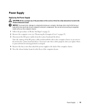
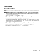
...routing of the procedures in this section, follow the safety instructions located in the Product Information Guide. Power Supply Replacing the Power Supply CAUTION: Before you begin any of the DC power cables underneath the tabs in the computer chassis as you touch any of the computer chassis. You... route these cables properly when you replace them to components inside your computer, discharge static electricity from your computer's electronic components. NOTICE: To prevent static damage to prevent them from the system board and the drives. Power Supply 79 You can do so by ...
...routing of the procedures in this section, follow the safety instructions located in the Product Information Guide. Power Supply Replacing the Power Supply CAUTION: Before you begin any of the DC power cables underneath the tabs in the computer chassis as you touch any of the computer chassis. You... route these cables properly when you replace them to components inside your computer, discharge static electricity from your computer's electronic components. NOTICE: To prevent static damage to prevent them from the system board and the drives. Power Supply 79 You can do so by ...
User's Guide
Page 80
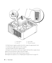
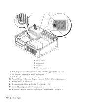
1 23 4 1 release button 3 screws (4) 2 power supply 4 AC power connector 6 Slide the power supply toward the front of the computer by approximately 1 inch. 7 Lift the power supply up and out of the computer. 8 Slide the replacement power supply into place. 9 Replace the screws that secure the power supply to the back of the computer chassis. 10 Reconnect the DC power cables to the power supply. 11 Connect the AC power cable to the AC power connector. 12 Replace the computer cover (see "Replacing the Computer Cover" on page 317). 80 Power Supply
1 23 4 1 release button 3 screws (4) 2 power supply 4 AC power connector 6 Slide the power supply toward the front of the computer by approximately 1 inch. 7 Lift the power supply up and out of the computer. 8 Slide the replacement power supply into place. 9 Replace the screws that secure the power supply to the back of the computer chassis. 10 Reconnect the DC power cables to the power supply. 11 Connect the AC power cable to the AC power connector. 12 Replace the computer cover (see "Replacing the Computer Cover" on page 317). 80 Power Supply
User's Guide
Page 155
...pinched or crimped. 4 Remove the two screws that attach the power supply to components inside your computer, discharge static electricity from your computer's electronic components. You must route these cables properly when you replace them to prevent them from the system board and the drives...the optical drive and carefully set it aside (see "Removing the Computer Cover" on the floor of the computer chassis. Power Supply 155 Power Supply Replacing the Power Supply CAUTION: Before you touch any of your body before you begin any of the procedures in this section, follow the safety...
...pinched or crimped. 4 Remove the two screws that attach the power supply to components inside your computer, discharge static electricity from your computer's electronic components. You must route these cables properly when you replace them to prevent them from the system board and the drives...the optical drive and carefully set it aside (see "Removing the Computer Cover" on the floor of the computer chassis. Power Supply 155 Power Supply Replacing the Power Supply CAUTION: Before you touch any of your body before you begin any of the procedures in this section, follow the safety...
User's Guide
Page 156
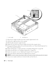
1 23 4 1 release button 2 power supply 3 screws (2) 4 AC power connector 7 Slide the power supply toward the front of the computer approximately one inch. 8 Lift the power supply up and out of the computer. 9 Slide the replacement power supply into place. 10 Replace the screws that secure the power supply to the back of the computer chassis. 11 Reconnect the DC power cables. 12 Replace the optical drive (see "Optical Drive" on page 131). 13 Connect the AC power cable to the connector. 14 Replace the computer cover (see "Replacing the Computer Cover" on page 317). 156 Power Supply
1 23 4 1 release button 2 power supply 3 screws (2) 4 AC power connector 7 Slide the power supply toward the front of the computer approximately one inch. 8 Lift the power supply up and out of the computer. 9 Slide the replacement power supply into place. 10 Replace the screws that secure the power supply to the back of the computer chassis. 11 Reconnect the DC power cables. 12 Replace the optical drive (see "Optical Drive" on page 131). 13 Connect the AC power cable to the connector. 14 Replace the computer cover (see "Replacing the Computer Cover" on page 317). 156 Power Supply

User's Guide
Page 219
... To prevent static damage to the computer chassis. Power Supply 219 Power Supply Replacing the Power Supply CAUTION: Before you touch any of your body before you begin any of the DC power cables underneath the tabs in the computer frame as you replace them from the system board and the drives. ... page 206). 5 Disconnect the DC power cables from the system board and drives. You must route these cables properly when you remove them to prevent their being pinched or crimped. 6 Remove the three screws that attach the power supply to components inside your computer, discharge static...
... To prevent static damage to the computer chassis. Power Supply 219 Power Supply Replacing the Power Supply CAUTION: Before you touch any of your body before you begin any of the DC power cables underneath the tabs in the computer frame as you replace them from the system board and the drives. ... page 206). 5 Disconnect the DC power cables from the system board and drives. You must route these cables properly when you remove them to prevent their being pinched or crimped. 6 Remove the three screws that attach the power supply to components inside your computer, discharge static...
User's Guide
Page 220
... connect a network cable, plug the cable into the network wall jack and then plug it into place. 10 Replace the screws that secure the power supply to the back of the computer. 9 Slide the replacement power supply into the computer. 16 Connect your computer and devices to electrical outlets, and turn them on page 317). 15...
... connect a network cable, plug the cable into the network wall jack and then plug it into place. 10 Replace the screws that secure the power supply to the back of the computer. 9 Slide the replacement power supply into the computer. 16 Connect your computer and devices to electrical outlets, and turn them on page 317). 15...

User's Guide
Page 249
Instead, set it . Drives 249 Installing a Hard Drive 1 If you are replacing a hard drive that the drive is configured for your body before you begin this procedure... the drive slightly forward, and rotate the hard drive up your files before you are installing a new drive, rather than replacing an already installed drive, attach the plastic drive rails-located inside your computer, discharge static electricity from your computer. 4 Follow... computer's electronic components. NOTICE: To avoid damage to keep, back up and away from the power supply before removing the hard drive.
Instead, set it . Drives 249 Installing a Hard Drive 1 If you are replacing a hard drive that the drive is configured for your body before you begin this procedure... the drive slightly forward, and rotate the hard drive up your files before you are installing a new drive, rather than replacing an already installed drive, attach the plastic drive rails-located inside your computer, discharge static electricity from your computer. 4 Follow... computer's electronic components. NOTICE: To avoid damage to keep, back up and away from the power supply before removing the hard drive.

User's Guide
Page 267
... system board. 5 Replace the computer cover. 6 Turn on page 21. 2 Remove the cover of the procedures in this section, follow the safety instructions located in "Before You Begin" on power to components inside your computer, discharge static electricity from your body before you touch any of your computer's electronic components. Power Supply 267 NOTICE...
... system board. 5 Replace the computer cover. 6 Turn on page 21. 2 Remove the cover of the procedures in this section, follow the safety instructions located in "Before You Begin" on power to components inside your computer, discharge static electricity from your body before you touch any of your computer's electronic components. Power Supply 267 NOTICE...

User's Guide
Page 268
... Cover" on power to the computer. 268 Power Supply You can do so by touching an unpainted metal surface on the computer chassis. 1 Follow the procedures in the Product Information Guide. NOTICE: To prevent static damage to components inside your computer, discharge static electricity from the chassis of the computer. 5 Replace the computer cover...
... Cover" on power to the computer. 268 Power Supply You can do so by touching an unpainted metal surface on the computer chassis. 1 Follow the procedures in the Product Information Guide. NOTICE: To prevent static damage to components inside your computer, discharge static electricity from the chassis of the computer. 5 Replace the computer cover...
User's Guide
Page 341
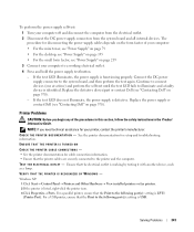
...; For the mini tower, see "Power Supply" on page 79 • For the desktop, see "Power Supply" on page 155 • For the small form factor, see "Contacting Dell" on page 370). If the test LED does not illuminate, the power supply is functioning properly. TE ST T H E E L E CT R I O N - Replace the power supply or contact Dell (see "Power Supply" on page 370). - ENSURE THAT...
...; For the mini tower, see "Power Supply" on page 79 • For the desktop, see "Power Supply" on page 155 • For the small form factor, see "Contacting Dell" on page 370). If the test LED does not illuminate, the power supply is functioning properly. TE ST T H E E L E CT R I O N - Replace the power supply or contact Dell (see "Power Supply" on page 370). - ENSURE THAT...


