
Quick Reference Guide
Page 4
... Removing the Computer Cover 55 Inside Your Computer 56 Cable Cover (Optional 57 System Board Components 59 Jumper Settings 60 Solving Problems 61 Dell Diagnostics 61 System Lights 65 Diagnostic Lights 66 Beep Codes 70 Resolving Software and Hardware Incompatibilities 72 Restoring Your Operating System 73 Using Microsoft Windows System Restore . . . . 73 Using...
... Removing the Computer Cover 55 Inside Your Computer 56 Cable Cover (Optional 57 System Board Components 59 Jumper Settings 60 Solving Problems 61 Dell Diagnostics 61 System Lights 65 Diagnostic Lights 66 Beep Codes 70 Resolving Software and Hardware Incompatibilities 72 Restoring Your Operating System 73 Using Microsoft Windows System Restore . . . . 73 Using...
Quick Reference Guide
Page 6
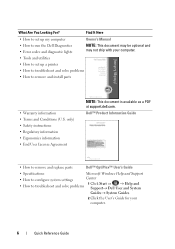
...to remove and replace parts Dell™ OptiPlex™ User's Guide • Specifications Microsoft Windows Help and Support • How to configure system settings Center • How to troubleshoot and solve problems 1 Click Start or → Help and Support→ Dell User and System Guides→...• How to set up a printer • How to troubleshoot and solve problems • How to run the Dell Diagnostics • Error codes and diagnostic lights NOTE: This document may be optional and may not ship with your computer. 6 Quick Reference Guide only) • Safety...
...to remove and replace parts Dell™ OptiPlex™ User's Guide • Specifications Microsoft Windows Help and Support • How to configure system settings Center • How to troubleshoot and solve problems 1 Click Start or → Help and Support→ Dell User and System Guides→...• How to set up a printer • How to troubleshoot and solve problems • How to run the Dell Diagnostics • Error codes and diagnostic lights NOTE: This document may be optional and may not ship with your computer. 6 Quick Reference Guide only) • Safety...
Quick Reference Guide
Page 17
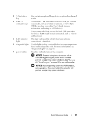
... 4 USB 2.0 connectors (2) Use the front USB connectors for devices that you connect occasionally, such as printers and keyboards. 5 LAN indicator light This light indicates that a LAN (local area network) connection is recommended that you use the back USB connectors for devices that typically remain connected, such... as joysticks or cameras, or for bootable USB devices (see "Diagnostic Lights" on page 66. 7 power button Press this button to turn off the computer by pressing the power button. It is established. 6...
... 4 USB 2.0 connectors (2) Use the front USB connectors for devices that you connect occasionally, such as printers and keyboards. 5 LAN indicator light This light indicates that a LAN (local area network) connection is recommended that you use the back USB connectors for devices that typically remain connected, such... as joysticks or cameras, or for bootable USB devices (see "Diagnostic Lights" on page 66. 7 power button Press this button to turn off the computer by pressing the power button. It is established. 6...
Quick Reference Guide
Page 18
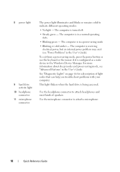
... sleep modes and pwoer-saving mode, see "Power Problems" in the User's Guide). Use the microphone connector to indicate different operating modes: • No light - To exit from a power-saving mode, press the power button or use the keyboard or the mouse if it is in the User's Guide. Use... the headphone connector to attach headphones and most kinds of light codes that can help you troubleshoot problems with your computer. The computer is being accessed. The computer is turned off. • Steady green - ...
... sleep modes and pwoer-saving mode, see "Power Problems" in the User's Guide). Use the microphone connector to indicate different operating modes: • No light - To exit from a power-saving mode, press the power button or use the keyboard or the mouse if it is in the User's Guide. Use... the headphone connector to attach headphones and most kinds of light codes that can help you troubleshoot problems with your computer. The computer is being accessed. The computer is turned off. • Steady green - ...

Quick Reference Guide
Page 21
...not detecting a physical connection to the network. 3 network adapter connector To attach your computer to ensure reliable operation. 4 network activity light Flashes a yellow light when the computer is recommended that you must use Category 3 wiring, force the network speed to 10 Mbps to a network or...such as printers and keyboards. A click indicates that typically remain connected, such as a cassette player, CD player, or VCR.; 2 link integrity light • Green - If you use of the network cable to the network adapter connector on " state. 5 line-out connector Use the green...
...not detecting a physical connection to the network. 3 network adapter connector To attach your computer to ensure reliable operation. 4 network activity light Flashes a yellow light when the computer is recommended that you must use Category 3 wiring, force the network speed to 10 Mbps to a network or...such as printers and keyboards. A click indicates that typically remain connected, such as a cassette player, CD player, or VCR.; 2 link integrity light • Green - If you use of the network cable to the network adapter connector on " state. 5 line-out connector Use the green...
Quick Reference Guide
Page 27
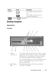
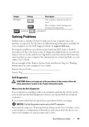
unjumpered Desktop Computer System Views Front View 1 2 3 11 10 1 USB 2.0 connectors (2) 2 LAN indicator light 9 8 76 5 4 Use the front USB connectors for devices that you use the back USB connectors for more information about booting to a USB device). ...is recommended that you connect occasionally, such as printers and keyboards. Jumper RTCRST Setting jumpered Description The real-time clock has not been reset. This light indicates that typically remain connected, such as joysticks or cameras, or for bootable USB devices (see "System Setup" in the User's Guide for ...
unjumpered Desktop Computer System Views Front View 1 2 3 11 10 1 USB 2.0 connectors (2) 2 LAN indicator light 9 8 76 5 4 Use the front USB connectors for devices that you use the back USB connectors for more information about booting to a USB device). ...is recommended that you connect occasionally, such as printers and keyboards. Jumper RTCRST Setting jumpered Description The real-time clock has not been reset. This light indicates that typically remain connected, such as joysticks or cameras, or for bootable USB devices (see "System Setup" in the User's Guide for ...
Quick Reference Guide
Page 28
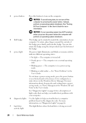
... different operating states: • No light - The computer is configured as a wake device in the User's Guide for a description of your operating system has ACPI enabled, when you press the power button the computer will perform an operating system shutdown. 4 Dell badge This badge can be rotated to... match the orientation of light codes that can also rotate the badge using the slot provided near the bottom of the badge, press firmly...
... different operating states: • No light - The computer is configured as a wake device in the User's Guide for a description of your operating system has ACPI enabled, when you press the power button the computer will perform an operating system shutdown. 4 Dell badge This badge can be rotated to... match the orientation of light codes that can also rotate the badge using the slot provided near the bottom of the badge, press firmly...

Quick Reference Guide
Page 31
...that typically remain connected, such as a cassette player, CD player, or VCR; A high volume of network traffic may make this light appear to be in /microphone connector to either a network jack or your network. The computer is transmitting or receiving network data. ... a record/playback device such as printers and keyboards. or a personal computer microphone for voice or musical input into the network connector. 2 link integrity light • Green - A good connection exists between a 100-Mbps network and the computer. • Yellow - A good connection exists between a ...
...that typically remain connected, such as a cassette player, CD player, or VCR; A high volume of network traffic may make this light appear to be in /microphone connector to either a network jack or your network. The computer is transmitting or receiving network data. ... a record/playback device such as printers and keyboards. or a personal computer microphone for voice or musical input into the network connector. 2 link integrity light • Green - A good connection exists between a 100-Mbps network and the computer. • Yellow - A good connection exists between a ...
Quick Reference Guide
Page 38
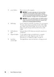
Instead, perform an operating system shutdown. 2 power button Press to turn on page 13 for more information, see "Diagnostic Lights" on the diagnostic code. NOTICE: To avoid losing data, do not turn the badge. See "Turning Off Your Computer" on the computer... the computer will perform an operating system shutdown. 3 Dell badge Can be rotated to help you troubleshoot a computer problem based on page 66. 6 hard drive activity light This light flickers when the hard drive is established. 5 diagnostic lights Use the lights to match the orientation of your computer. You can ...
Instead, perform an operating system shutdown. 2 power button Press to turn on page 13 for more information, see "Diagnostic Lights" on the diagnostic code. NOTICE: To avoid losing data, do not turn the badge. See "Turning Off Your Computer" on the computer... the computer will perform an operating system shutdown. 3 Dell badge Can be rotated to help you troubleshoot a computer problem based on page 66. 6 hard drive activity light This light flickers when the hard drive is established. 5 diagnostic lights Use the lights to match the orientation of your computer. You can ...
Quick Reference Guide
Page 39
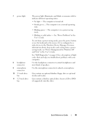
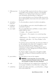
... a power-saving mode, press the power button or use the keyboard or the mouse if it is turned off. • Steady green - See "Dell Diagnostics" on page 61 for Windows XP and Vista" in a power-saving mode. • Blinking or solid amber - To exit from a powersaving ... the User's Guide. Insert a CD or DVD (if supported) into this drive. 7 power light 8 headphone connector 9 microphone connector 10 3.5-inch drive bay 11 5.25-inch drive bay The power light illuminates and blinks or remains solid to attach a microphone. Quick Reference Guide 39 The computer is configured...
... a power-saving mode, press the power button or use the keyboard or the mouse if it is turned off. • Steady green - See "Dell Diagnostics" on page 61 for Windows XP and Vista" in a power-saving mode. • Blinking or solid amber - To exit from a powersaving ... the User's Guide. Insert a CD or DVD (if supported) into this drive. 7 power light 8 headphone connector 9 microphone connector 10 3.5-inch drive bay 11 5.25-inch drive bay The power light illuminates and blinks or remains solid to attach a microphone. Quick Reference Guide 39 The computer is configured...

Quick Reference Guide
Page 41
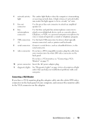
A good connection exists between a 100-Mbps network and the computer. • Yellow - For more information, see "System Setup Options" in the User's Guide. 2 link integrity light • Green - If you have a USB printer, plug it into a USB connector. The computer is automatically disabled if the computer detects an installed card containing a ...
A good connection exists between a 100-Mbps network and the computer. • Yellow - For more information, see "System Setup Options" in the User's Guide. 2 link integrity light • Green - If you have a USB printer, plug it into a USB connector. The computer is automatically disabled if the computer detects an installed card containing a ...

Quick Reference Guide
Page 42
... use of the onboard NIC. It is transmitting or receiving network data. A high volume of network traffic may make this light appear to be in /microphone connector (available on computers with integrated sound) to attach headphones and most speakers with integrated sound...device such as printers and keyboards. 42 Quick Reference Guide Use the back USB connectors for your network. 3 network adapter connector 4 network activity light 5 line-out connector 6 linein/microphone connector 7 USB 2.0 connectors (6) To attach your computer to a network or broadband device, connect one...
... use of the onboard NIC. It is transmitting or receiving network data. A high volume of network traffic may make this light appear to be in /microphone connector (available on computers with integrated sound) to attach headphones and most speakers with integrated sound...device such as printers and keyboards. 42 Quick Reference Guide Use the back USB connectors for your network. 3 network adapter connector 4 network activity light 5 line-out connector 6 linein/microphone connector 7 USB 2.0 connectors (6) To attach your computer to a network or broadband device, connect one...
Quick Reference Guide
Page 49
... "Power Problems" in the module bay. The computer is in the User's Guide. Press this button to indicate different states: • No light - See "Turning Off Your Computer" on page 13 for Windows XP and Vista" in a normal operating state. • Blinking green - It... 65 for devices that typically remain connected, such as printers and keyboards. See "System Lights" on the computer. Quick Reference Guide 49 1 USB connectors (2) 2 microphone connector 3 headphone connector 4 power light 5 power button 6 vents 7 module bay Use the front USB connectors for devices that...
... "Power Problems" in the module bay. The computer is in the User's Guide. Press this button to indicate different states: • No light - See "Turning Off Your Computer" on page 13 for Windows XP and Vista" in a normal operating state. • Blinking green - It... 65 for devices that typically remain connected, such as printers and keyboards. See "System Lights" on the computer. Quick Reference Guide 49 1 USB connectors (2) 2 microphone connector 3 headphone connector 4 power light 5 power button 6 vents 7 module bay Use the front USB connectors for devices that...

Quick Reference Guide
Page 50
... when devices such as your CD player are operating. 9 vents The vents help prevent your computer from or writes data to the hard drive. The light might also be on each side of the computer help prevent your computer from overheating. 8 hard drive access The hard drive access...
... when devices such as your CD player are operating. 9 vents The vents help prevent your computer from or writes data to the hard drive. The light might also be on each side of the computer help prevent your computer from overheating. 8 hard drive access The hard drive access...
Quick Reference Guide
Page 51
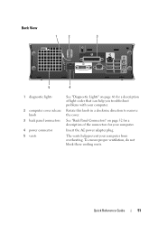
... "Back Panel Connectors" on page 66 for a description of the connectors for a description of light codes that can help prevent your computer. Back View 1 2 3 5 4 1 diagnostic lights 2 computer cover release knob 3 back panel connectors 4 power connector 5 vents See "Diagnostic Lights" on page 52 for your computer from overheating. Rotate this knob in a clockwise direction...
... "Back Panel Connectors" on page 66 for a description of the connectors for a description of light codes that can help prevent your computer. Back View 1 2 3 5 4 1 diagnostic lights 2 computer cover release knob 3 back panel connectors 4 power connector 5 vents See "Diagnostic Lights" on page 52 for your computer from overheating. Rotate this knob in a clockwise direction...

Quick Reference Guide
Page 52
NOTE: Do not plug a telephone cable into a USB connector. 2 link integrity light • Green - A click indicates that you use Category 3 wiring, force the network speed to 10 Mbps to ensure reliable operation. 52 Quick Reference Guide If ...
NOTE: Do not plug a telephone cable into a USB connector. 2 link integrity light • Green - A click indicates that you use Category 3 wiring, force the network speed to 10 Mbps to ensure reliable operation. 52 Quick Reference Guide If ...
Quick Reference Guide
Page 53
...personal computer microphone for voice or musical input into a sound or telephony program. 7 USB connectors Use the back USB connectors for a description of light codes that typically (5) remain connected, such as printers and keyboards. 8 serial connector Connect a serial device, such as a cassette player, connector... monitor, see "Connecting a VGA Monitor" on page 53. 10 power connector Insert the AC power adapter plug. 11 diagnostic lights See "Diagnostic Lights" on page 66 for devices that can help you have a DVI-compatible monitor, plug the cable from your computer, and ...
...personal computer microphone for voice or musical input into a sound or telephony program. 7 USB connectors Use the back USB connectors for a description of light codes that typically (5) remain connected, such as printers and keyboards. 8 serial connector Connect a serial device, such as a cassette player, connector... monitor, see "Connecting a VGA Monitor" on page 53. 10 power connector Insert the AC power adapter plug. 11 diagnostic lights See "Diagnostic Lights" on page 66 for devices that can help you have a DVI-compatible monitor, plug the cable from your computer, and ...
Quick Reference Guide
Page 61
...example of the error, beep codes, or diagnostics light patterns, record your Express Service Code and Service Tag below, and then contact Dell from the same location as expected. NOTICE: The Dell Diagnostics works only on contacting Dell, see "Finding Information" in system setup and ... computer User's Guide. For the latest troubleshooting information available for technical assistance. Enter system setup (see the Dell Support website at support.dell.com. If computer problems occur that you print these procedures before you begin . Jumper RTCRST Setting jumpered Description...
...example of the error, beep codes, or diagnostics light patterns, record your Express Service Code and Service Tag below, and then contact Dell from the same location as expected. NOTICE: The Dell Diagnostics works only on contacting Dell, see "Finding Information" in system setup and ... computer User's Guide. For the latest troubleshooting information available for technical assistance. Enter system setup (see the Dell Support website at support.dell.com. If computer problems occur that you print these procedures before you begin . Jumper RTCRST Setting jumpered Description...
Quick Reference Guide
Page 65
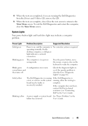
...to the Main Menu screen. On the desktop computer, a solid green light indicates a network connection. Solid yellow The Dell Diagnostics is running If the Dell Diagnostics is required. Power Light Problem Description Suggested Resolution Solid green Power is on, and the computer...close the Main Menu screen. If the computer does not boot, contact Dell for technical assistance (see "Contacting Dell" in the failure has occurred. System Lights Your power button light and hard drive light may be faulty or complete. incorrectly installed. Blinking yellow A power supply...
...to the Main Menu screen. On the desktop computer, a solid green light indicates a network connection. Solid yellow The Dell Diagnostics is running If the Dell Diagnostics is required. Power Light Problem Description Suggested Resolution Solid green Power is on, and the computer...close the Main Menu screen. If the computer does not boot, contact Dell for technical assistance (see "Contacting Dell" in the failure has occurred. System Lights Your power button light and hard drive light may be faulty or complete. incorrectly installed. Blinking yellow A power supply...
Quick Reference Guide
Page 66
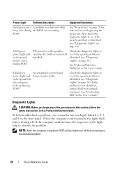
...see if the specific problem is not identified, contact Dell for instructions on the front panel. POST See "Beep Codes" on page 70 for technical assistance (see "Diagnostic Lights" on page 66). identified (see "Contacting Dell" in the User's Guide. no video during ...POST Check the diagnostic lights to see if the specific problem is identified (see "Diagnostic Lights" on page 66). When the computer starts normally, the lights flash before booting...
...see if the specific problem is not identified, contact Dell for instructions on the front panel. POST See "Beep Codes" on page 70 for technical assistance (see "Diagnostic Lights" on page 66). identified (see "Contacting Dell" in the User's Guide. no video during ...POST Check the diagnostic lights to see if the specific problem is identified (see "Diagnostic Lights" on page 66). When the computer starts normally, the lights flash before booting...


