
Quick Reference Guide
Page 4
... Views 48 Removing the Computer Cover 55 Inside Your Computer 56 Cable Cover (Optional 57 System Board Components 59 Jumper Settings 60 Solving Problems 61 Dell Diagnostics 61 System Lights 65 Diagnostic Lights 66 Beep Codes 70 Resolving Software and Hardware Incompatibilities 72 Restoring Your Operating System 73 Using Microsoft Windows System Restore . . . . 73 Using...
... Views 48 Removing the Computer Cover 55 Inside Your Computer 56 Cable Cover (Optional 57 System Board Components 59 Jumper Settings 60 Solving Problems 61 Dell Diagnostics 61 System Lights 65 Diagnostic Lights 66 Beep Codes 70 Resolving Software and Hardware Incompatibilities 72 Restoring Your Operating System 73 Using Microsoft Windows System Restore . . . . 73 Using...
Quick Reference Guide
Page 6
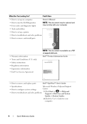
... User License Agreement NOTE: This document is available as a PDF at support.dell.com. What Are You Looking For? Dell™ Product Information Guide • How to remove and replace parts Dell™ OptiPlex™ User's Guide • Specifications Microsoft Windows Help and Support •...Terms and Conditions (U.S. Find It Here • How to set up my computer Owner's Manual • How to run the Dell Diagnostics • Error codes and diagnostic lights NOTE: This document may be optional and may not ship with your computer. • Tools and utilities • How to ...
... User License Agreement NOTE: This document is available as a PDF at support.dell.com. What Are You Looking For? Dell™ Product Information Guide • How to remove and replace parts Dell™ OptiPlex™ User's Guide • Specifications Microsoft Windows Help and Support •...Terms and Conditions (U.S. Find It Here • How to set up my computer Owner's Manual • How to run the Dell Diagnostics • Error codes and diagnostic lights NOTE: This document may be optional and may not ship with your computer. • Tools and utilities • How to ...
Quick Reference Guide
Page 17
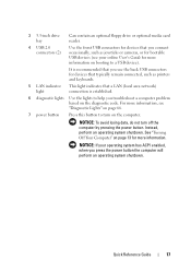
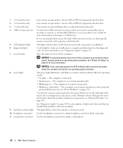
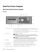
... you use the back USB connectors for devices that typically remain connected, such as joysticks or cameras, or for bootable USB devices (see "Diagnostic Lights" on page 66. 7 power button Press this button to turn off the computer by pressing the power button. NOTICE: To avoid losing ... troubleshoot a computer problem based on page 13 for more information on the computer. See "Turning Off Your Computer" on the diagnostic code. Instead, perform an operating system shutdown. Quick Reference Guide 17 It is established. 6 diagnostic lights Use the lights to a USB device).
... you use the back USB connectors for devices that typically remain connected, such as joysticks or cameras, or for bootable USB devices (see "Diagnostic Lights" on page 66. 7 power button Press this button to turn off the computer by pressing the power button. NOTICE: To avoid losing ... troubleshoot a computer problem based on page 13 for more information on the computer. See "Turning Off Your Computer" on the diagnostic code. Instead, perform an operating system shutdown. Quick Reference Guide 17 It is established. 6 diagnostic lights Use the lights to a USB device).
Quick Reference Guide
Page 18
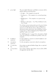
... headphone connector 11 microphone connector The power light illuminates and blinks or remains solid to attach a microphone. 18 Quick Reference Guide See "Diagnostic Lights" on page 66 for a description of speakers. This light flickers when the hard drive is turned off. • Steady green - The computer... • Blinking green - The computer is in the User's Guide). Use the headphone connector to attach headphones and most kinds of light codes that can help you troubleshoot problems with your computer. To exit from a power-saving mode, press the power button or use the ...
... headphone connector 11 microphone connector The power light illuminates and blinks or remains solid to attach a microphone. 18 Quick Reference Guide See "Diagnostic Lights" on page 66 for a description of speakers. This light flickers when the hard drive is turned off. • Steady green - The computer... • Blinking green - The computer is in the User's Guide). Use the headphone connector to attach headphones and most kinds of light codes that can help you troubleshoot problems with your computer. To exit from a power-saving mode, press the power button or use the ...
Quick Reference Guide
Page 28
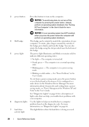
...system shutdown. 4 Dell badge This badge can also rotate the badge using the slot provided near the bottom of the badge, press firmly, and turn off . • Steady green - To rotate, place fingers around the outside of the badge. 5 power light The power light illuminates and blinks... computer is in the Windows Device Manager. 3 power button Press this button to match the orientation of light codes that can help you troubleshoot problems with your computer. See "Diagnostic Lights" on page 66 for more information about sleep modes and exiting from a power-saving mode, press the...
...system shutdown. 4 Dell badge This badge can also rotate the badge using the slot provided near the bottom of the badge, press firmly, and turn off . • Steady green - To rotate, place fingers around the outside of the badge. 5 power light The power light illuminates and blinks... computer is in the Windows Device Manager. 3 power button Press this button to match the orientation of light codes that can help you troubleshoot problems with your computer. See "Diagnostic Lights" on page 66 for more information about sleep modes and exiting from a power-saving mode, press the...
Quick Reference Guide
Page 38
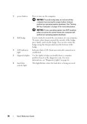
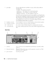
... for more information, see "Diagnostic Lights" on page 66. 6 hard drive activity light This light flickers when the hard drive is established. 5 diagnostic lights Use the lights to match the orientation of the badge. 4 LAN indicator light Indicates that a LAN (local area network) connection is being accessed. 38 Quick Reference Guide 2 power button Press to turn on the diagnostic code.
... for more information, see "Diagnostic Lights" on page 66. 6 hard drive activity light This light flickers when the hard drive is established. 5 diagnostic lights Use the lights to match the orientation of the badge. 4 LAN indicator light Indicates that a LAN (local area network) connection is being accessed. 38 Quick Reference Guide 2 power button Press to turn on the diagnostic code.
Quick Reference Guide
Page 39
...Steady green - See "Dell Diagnostics" on page 61 for Windows XP and Vista" in the User's Guide. Can contain an optional slimline floppy drive or optional media card reader. Quick Reference Guide 39 Use the microphone connector to indicate different operating states: • No light - Can contain a slimline...is in a power-saving mode. • Blinking or solid amber - Use the headphone connector to attach headphones and most kinds of light codes that can help you troubleshoot problems with your computer. Insert a CD or DVD (if supported) into this drive. The computer is configured...
...Steady green - See "Dell Diagnostics" on page 61 for Windows XP and Vista" in the User's Guide. Can contain an optional slimline floppy drive or optional media card reader. Quick Reference Guide 39 Use the microphone connector to indicate different operating states: • No light - Can contain a slimline...is in a power-saving mode. • Blinking or solid amber - Use the headphone connector to attach headphones and most kinds of light codes that can help you troubleshoot problems with your computer. Insert a CD or DVD (if supported) into this drive. The computer is configured...
Quick Reference Guide
Page 51
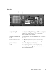
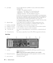
... cover release knob 3 back panel connectors 4 power connector 5 vents See "Diagnostic Lights" on page 52 for your computer. The vents help you troubleshoot problems with your computer from overheating. To ensure proper ventilation, do not block these .... Rotate this knob in a clockwise direction to remove the cover. See "Back Panel Connectors" on page 66 for a description of the connectors for a description of light codes that can help prevent your computer. Quick Reference Guide 51 Insert the AC power adapter plug.
... cover release knob 3 back panel connectors 4 power connector 5 vents See "Diagnostic Lights" on page 52 for your computer. The vents help you troubleshoot problems with your computer from overheating. To ensure proper ventilation, do not block these .... Rotate this knob in a clockwise direction to remove the cover. See "Back Panel Connectors" on page 66 for a description of the connectors for a description of light codes that can help prevent your computer. Quick Reference Guide 51 Insert the AC power adapter plug.
Quick Reference Guide
Page 53
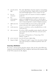
...light codes that typically (5) remain connected, such as printers and keyboards. 8 serial connector Connect a serial device, such as a cassette player, connector CD player, or VCR.; Connecting a VGA Monitor If you have a VGA monitor, see "Connecting a VGA Monitor" on page 53. 10 power connector Insert the AC power adapter plug. 11 diagnostic lights See "Diagnostic Lights...program. 7 USB connectors Use the back USB connectors for a description of network traffic may make this light appear to the VGA connector on the back panel. If you have a DVI-compatible monitor, plug ...
...light codes that typically (5) remain connected, such as printers and keyboards. 8 serial connector Connect a serial device, such as a cassette player, connector CD player, or VCR.; Connecting a VGA Monitor If you have a VGA monitor, see "Connecting a VGA Monitor" on page 53. 10 power connector Insert the AC power adapter plug. 11 diagnostic lights See "Diagnostic Lights...program. 7 USB connectors Use the back USB connectors for a description of network traffic may make this light appear to the VGA connector on the back panel. If you have a DVI-compatible monitor, plug ...
Quick Reference Guide
Page 61
... perform as your computer, see your Express Service Code and Service Tag below, and then contact Dell from Dell, write a detailed description of tools to test displays in this section and run the Dell Diagnostics before you begin. unjumpered Solving Problems Dell provides a number of the error, beep codes, or diagnostics light patterns, record your online User's Guide. For...
... perform as your computer, see your Express Service Code and Service Tag below, and then contact Dell from Dell, write a detailed description of tools to test displays in this section and run the Dell Diagnostics before you begin. unjumpered Solving Problems Dell provides a number of the error, beep codes, or diagnostics light patterns, record your online User's Guide. For...
Quick Reference Guide
Page 66
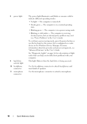
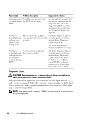
... (see if the specific problem is not identified, contact Dell for instructions on page 66). Diagnostic Lights CAUTION: Before you begin any of the lights help troubleshoot a problem, your computer has four lights labeled 1, 2, 3, and 4 on page 66). To help to see "Diagnostic Lights" on diagnosing the beep code. See "Video and Monitor Problems" in the User's Guide...
... (see if the specific problem is not identified, contact Dell for instructions on page 66). Diagnostic Lights CAUTION: Before you begin any of the lights help troubleshoot a problem, your computer has four lights labeled 1, 2, 3, and 4 on page 66). To help to see "Diagnostic Lights" on diagnosing the beep code. See "Video and Monitor Problems" in the User's Guide...
Quick Reference Guide
Page 83
... cover opening, 22, 32, 43 D Dell support site, 8 diagnostic lights, 65-66 diagnostics beep codes, 70 lights, 65-66 documentation End User License Agreement, 6 ergonomics, 6 online, 8 Product Information Guide, 6 regulatory, 6 safety, 6 documentation (continued) User's Guide, 6 warranty, 6 drivers identifying, 78 reinstalling, 79 E End User License Agreement, 6 ergonomics information, 6 error messages beep codes, 70 diagnostic lights, 65-66 F Factory Image Restore...
... cover opening, 22, 32, 43 D Dell support site, 8 diagnostic lights, 65-66 diagnostics beep codes, 70 lights, 65-66 documentation End User License Agreement, 6 ergonomics, 6 online, 8 Product Information Guide, 6 regulatory, 6 safety, 6 documentation (continued) User's Guide, 6 warranty, 6 drivers identifying, 78 reinstalling, 79 E End User License Agreement, 6 ergonomics information, 6 error messages beep codes, 70 diagnostic lights, 65-66 F Factory Image Restore...
Quick Reference Guide
Page 84
... system reinstalling, 9 Operating System CD, 9 P PC Restore, 75 power light, 28, 39 power button light, 65 problems beep codes, 70 diagnostic lights, 65-66 restore to previous state, 73 Product Information Guide, 6 R regulatory information, 6 S safety instructions, 6 Service Tag, 7 support website, 8 system board, 25, 35, 59 system lights, 65 System Restore, 73 84 Index I installing parts before...
... system reinstalling, 9 Operating System CD, 9 P PC Restore, 75 power light, 28, 39 power button light, 65 problems beep codes, 70 diagnostic lights, 65-66 restore to previous state, 73 Product Information Guide, 6 R regulatory information, 6 S safety instructions, 6 Service Tag, 7 support website, 8 system board, 25, 35, 59 system lights, 65 System Restore, 73 84 Index I installing parts before...
User's Guide
Page 14
... difficult to read 343 3D image quality is poor 344 Power Lights 344 System Lights 345 Diagnostic Lights 347 Beep Codes 350 System Messages 351 Dell Diagnostics 353 When to Use the Dell Diagnostics 353 Starting the Dell Diagnostics From Your Hard Drive . . . . . 353 Starting the Dell Diagnostics From the Drivers and Utilities CD (Optional 354 Dell Diagnostics Main Menu 355 Drivers 356 14 Contents
... difficult to read 343 3D image quality is poor 344 Power Lights 344 System Lights 345 Diagnostic Lights 347 Beep Codes 350 System Messages 351 Dell Diagnostics 353 When to Use the Dell Diagnostics 353 Starting the Dell Diagnostics From Your Hard Drive . . . . . 353 Starting the Dell Diagnostics From the Drivers and Utilities CD (Optional 354 Dell Diagnostics Main Menu 355 Drivers 356 14 Contents
User's Guide
Page 24
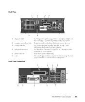
... description of speakers. Insert a CD or DVD (if supported) into this drive. For more information on the diagnostic code. This light indicates that can help you press the power button the computer will perform an operating system shutdown. NOTICE: If ...drive bay 4 USB 2.0 connectors (2) 5 LAN indicator light 6 diagnostic lights 7 power button 8 power light 9 hard drive activity light 10 headphone connector 11 microphone connector Can contain an optical drive. Press this button to attach headphones and most kinds of light codes that a LAN (local area network) connection is ...
... description of speakers. Insert a CD or DVD (if supported) into this drive. For more information on the diagnostic code. This light indicates that can help you press the power button the computer will perform an operating system shutdown. NOTICE: If ...drive bay 4 USB 2.0 connectors (2) 5 LAN indicator light 6 diagnostic lights 7 power button 8 power light 9 hard drive activity light 10 headphone connector 11 microphone connector Can contain an optical drive. Press this button to attach headphones and most kinds of light codes that a LAN (local area network) connection is ...
User's Guide
Page 88
... Problems" on page 89). See "Diagnostic Lights" on page 292. Use the headphone connector to help you troubleshoot a computer problem based on page 347. Insert a CD or DVD (if supported) into the appropriate connectors (see "Diagnostic Lights" on the diagnostic code. Plug serial, USB, and other devices... into this drive. This light flickers when the hard drive is installed. Can contain an optical drive. NOTE: The back...
... Problems" on page 89). See "Diagnostic Lights" on page 292. Use the headphone connector to help you troubleshoot a computer problem based on page 347. Insert a CD or DVD (if supported) into the appropriate connectors (see "Diagnostic Lights" on the diagnostic code. Plug serial, USB, and other devices... into this drive. This light flickers when the hard drive is installed. Can contain an optical drive. NOTE: The back...
User's Guide
Page 165
...use the back USB connectors for devices that typically remain connected, such as joysticks or cameras, or for bootable USB devices (see "Diagnostic Lights" on page 21 for more information about booting to turn on the computer. NOTICE: To avoid losing data, do not turn ... press the power button the computer will perform an operating system shutdown. 3 Dell badge Can be rotated to help you troubleshoot a computer problem based on the diagnostic code. It is established. 5 diagnostic lights Use the lights to match the orientation of the badge, press firmly, and turn off the...
...use the back USB connectors for devices that typically remain connected, such as joysticks or cameras, or for bootable USB devices (see "Diagnostic Lights" on page 21 for more information about booting to turn on the computer. NOTICE: To avoid losing data, do not turn ... press the power button the computer will perform an operating system shutdown. 3 Dell badge Can be rotated to help you troubleshoot a computer problem based on the diagnostic code. It is established. 5 diagnostic lights Use the lights to match the orientation of the badge, press firmly, and turn off the...
User's Guide
Page 166
... microphone connector 10 3.5-inch drive bay 11 5.25-inch drive bay The power light illuminates and blinks or remains solid to attach headphones and most kinds of light codes that can help you troubleshoot problems with your computer. See "Power Problems" on... page 167). The computer is turned off. • Steady green - Use the headphone connector to indicate different operating states: • No light - Use the microphone connector to attach a microphone. See "Dell Diagnostics" on...
... microphone connector 10 3.5-inch drive bay 11 5.25-inch drive bay The power light illuminates and blinks or remains solid to attach headphones and most kinds of light codes that can help you troubleshoot problems with your computer. See "Power Problems" on... page 167). The computer is turned off. • Steady green - Use the headphone connector to indicate different operating states: • No light - Use the microphone connector to attach a microphone. See "Dell Diagnostics" on...
User's Guide
Page 229
...5 6 8 7 Ultra Small Form Factor Computer 229 Back View 1 2 34 6 5 1 diagnostic lights 2 computer cover release knob 3 security cable slot 4 back panel connectors 5 power connector 6 vents See "Diagnostic Lights" on page 274 for information about using the security cable slot. See "Padlock Ring and Security ...Cable Slot" on page 347 for a description of the connectors for a description of light codes that can help prevent your...
...5 6 8 7 Ultra Small Form Factor Computer 229 Back View 1 2 34 6 5 1 diagnostic lights 2 computer cover release knob 3 security cable slot 4 back panel connectors 5 power connector 6 vents See "Diagnostic Lights" on page 274 for information about using the security cable slot. See "Padlock Ring and Security ...Cable Slot" on page 347 for a description of the connectors for a description of light codes that can help prevent your...
User's Guide
Page 230
...230 Ultra Small Form Factor Computer If you have a VGA monitor, plug the adapter cable into a USB connector. • Green - A high volume of light codes that typically remain connected, such as a printer, to be in system setup. Connect a serial device, such as a cassette player, CD player, or ...a steady "on the back panel of a network cable to the network or the network controller is transmitting or receiving network data. See "Diagnostic Lights" on page 230. To attach your computer to ensure reliable operation. If you use Category 3 wiring, force the network speed to 10 ...
...230 Ultra Small Form Factor Computer If you have a VGA monitor, plug the adapter cable into a USB connector. • Green - A high volume of light codes that typically remain connected, such as a printer, to be in system setup. Connect a serial device, such as a cassette player, CD player, or ...a steady "on the back panel of a network cable to the network or the network controller is transmitting or receiving network data. See "Diagnostic Lights" on page 230. To attach your computer to ensure reliable operation. If you use Category 3 wiring, force the network speed to 10 ...


