Quick Reference Guide
Page 3
... Cover 13 Before You Begin 13 Mini Tower Computer 14 Inside Your Computer 16 Mini Tower Computer 16 Setting Up Your Computer 19 Set Up Your Keyboard and Mouse 20 Set Up Your Monitor 20 Power Connections 21 Solving Problems 21 Dell Diagnostics 21 System Lights 24 Diagnostic Lights ...and Hardware Incompatibilities 28 Using Microsoft Windows XP System Restore 28 Reinstalling Microsoft Windows XP 30 Microsoft® Windows Vista 32 The support.dell.com user interface may vary depending on your selections 34 Using the Drivers and Utilities CD 34 Drivers for Your Computer 34 Index ...
... Cover 13 Before You Begin 13 Mini Tower Computer 14 Inside Your Computer 16 Mini Tower Computer 16 Setting Up Your Computer 19 Set Up Your Keyboard and Mouse 20 Set Up Your Monitor 20 Power Connections 21 Solving Problems 21 Dell Diagnostics 21 System Lights 24 Diagnostic Lights ...and Hardware Incompatibilities 28 Using Microsoft Windows XP System Restore 28 Reinstalling Microsoft Windows XP 30 Microsoft® Windows Vista 32 The support.dell.com user interface may vary depending on your selections 34 Using the Drivers and Utilities CD 34 Drivers for Your Computer 34 Index ...
Quick Reference Guide
Page 11
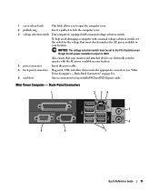
...power connector Insert the power cable. 5 back-panel connectors Plug serial, USB, and other devices into the appropriate connectors (see "Mini Tower Computer - Back-Panel Connectors" on page 11). 6 card slots Access connectors for the voltage that your monitor and attached devices are electrically...the computer cover. 2 padlock ring Insert a padlock to the 115-V position even though the AC power available in your location. Mini Tower Computer - To help avoid damaging a computer with a manual voltage-selection switch. NOTICE: The voltage selection switch must be set the ...
...power connector Insert the power cable. 5 back-panel connectors Plug serial, USB, and other devices into the appropriate connectors (see "Mini Tower Computer - Back-Panel Connectors" on page 11). 6 card slots Access connectors for the voltage that your monitor and attached devices are electrically...the computer cover. 2 padlock ring Insert a padlock to the 115-V position even though the AC power available in your location. Mini Tower Computer - To help avoid damaging a computer with a manual voltage-selection switch. NOTICE: The voltage selection switch must be set the ...

Quick Reference Guide
Page 14
... Disconnect your computer and all attached devices from the electrical outlet before removing the cover. 5 Remove the computer cover. See "Mini Tower Computer" on a soft nonabrasive surface. NOTICE: Before touching anything inside your computer, ground yourself by touching an unpainted metal surface, such... release latch shown in the Product Information Guide. CAUTION: Graphic card heatsinks may become very hot during normal operation. Mini Tower Computer CAUTION: Before you begin any static electricity that a graphic card heatsink has had sufficient time to dissipate any of the...
... Disconnect your computer and all attached devices from the electrical outlet before removing the cover. 5 Remove the computer cover. See "Mini Tower Computer" on a soft nonabrasive surface. NOTICE: Before touching anything inside your computer, ground yourself by touching an unpainted metal surface, such... release latch shown in the Product Information Guide. CAUTION: Graphic card heatsinks may become very hot during normal operation. Mini Tower Computer CAUTION: Before you begin any static electricity that a graphic card heatsink has had sufficient time to dissipate any of the...


