Quick Reference Guide
Page 49
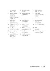
1 fan connector (FAN_CPU) 2 processor socket (CPU) 4 memory module 5 power connector connectors (POWER1) (DIMM_1, DIMM_2, DIMM_3, DIMM_4) 7 front-panel connector (FRONTPANEL) 8 fan connector (FAN_HDD) 10 CMOS reset jumper 11 battery socket (RTCRST) (BATTERY) 13 standby 14 PCI Express x16 (AUX_PWR_LED) connector (SLOT1) 16 password jumper (PSWD) 17 serial connector (PS2/SER2) 19 ...
1 fan connector (FAN_CPU) 2 processor socket (CPU) 4 memory module 5 power connector connectors (POWER1) (DIMM_1, DIMM_2, DIMM_3, DIMM_4) 7 front-panel connector (FRONTPANEL) 8 fan connector (FAN_HDD) 10 CMOS reset jumper 11 battery socket (RTCRST) (BATTERY) 13 standby 14 PCI Express x16 (AUX_PWR_LED) connector (SLOT1) 16 password jumper (PSWD) 17 serial connector (PS2/SER2) 19 ...
User's Guide
Page 102
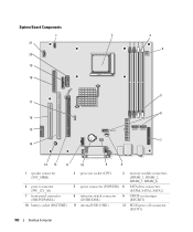
System Board Components 1 21 20 19 18 17 16 15 14 2 3 DIMM 1 DIMM 2 DIMM 3 DIMM 4 4 SATA 2 5 6 SATA 1 SATA 0 7 13 12 11 10 9 8 1 speaker connector (INT_SPKR) 4 power connector (PW_12V_A1) 7 front-panel connector (FRONTPANEL) 10 battery socket (BATTERY) 2 processor socket (CPU) 3 memory module connectors (DIMM_1, DIMM_2, DIMM_3, DIMM_4) 5 power connector (POWER1) 6 SATA drive connectors (SATA0, SATA1, SATA2) 8 intrusion switch connector (INTRUDER) 9 CMOS reset jumper (RTCRST) 11 internal USB (USB1) 12 PCI Express x16 connector (SLOT1) 102 Desktop Computer
System Board Components 1 21 20 19 18 17 16 15 14 2 3 DIMM 1 DIMM 2 DIMM 3 DIMM 4 4 SATA 2 5 6 SATA 1 SATA 0 7 13 12 11 10 9 8 1 speaker connector (INT_SPKR) 4 power connector (PW_12V_A1) 7 front-panel connector (FRONTPANEL) 10 battery socket (BATTERY) 2 processor socket (CPU) 3 memory module connectors (DIMM_1, DIMM_2, DIMM_3, DIMM_4) 5 power connector (POWER1) 6 SATA drive connectors (SATA0, SATA1, SATA2) 8 intrusion switch connector (INTRUDER) 9 CMOS reset jumper (RTCRST) 11 internal USB (USB1) 12 PCI Express x16 connector (SLOT1) 102 Desktop Computer
User's Guide
Page 266
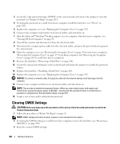
...hard drive ("Installing a Hard Drive" on page 210). 14 Replace the computer cover (see "Replacing the Computer Cover" on page 297). NOTE: CMOS settings will not be cleared, if power is assigned (see "Entering System Setup" on page 257). 16 Assign a new system and/or administrator ... section, follow the safety instructions located in the Product Information Guide. 1 Follow the procedures in "Before You Begin" on page 208). 3 Reset the current CMOS settings: 266 Advanced Features 3 Locate the 2-pin password jumper (PSWD) on the system board, and remove the jumper to clear the password ...
...hard drive ("Installing a Hard Drive" on page 210). 14 Replace the computer cover (see "Replacing the Computer Cover" on page 297). NOTE: CMOS settings will not be cleared, if power is assigned (see "Entering System Setup" on page 257). 16 Assign a new system and/or administrator ... section, follow the safety instructions located in the Product Information Guide. 1 Follow the procedures in "Before You Begin" on page 208). 3 Reset the current CMOS settings: 266 Advanced Features 3 Locate the 2-pin password jumper (PSWD) on the system board, and remove the jumper to clear the password ...


