Quick Reference Guide
Page 9
..., patches, and software updates • Desktop System Software (DSS) - system and installs the updates NOTE: The support.dell.com user interface appropriate for your selections. Upgrade information for Dell™ 3.5-inch USB floppy drives, processors, optical drives, and USB devices. support for components, such as memory, the hard drive, and the operating system...
..., patches, and software updates • Desktop System Software (DSS) - system and installs the updates NOTE: The support.dell.com user interface appropriate for your selections. Upgrade information for Dell™ 3.5-inch USB floppy drives, processors, optical drives, and USB devices. support for components, such as memory, the hard drive, and the operating system...
Quick Reference Guide
Page 33
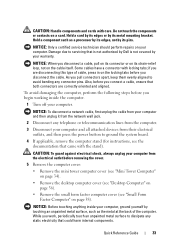
... working inside your computer from their electrical outlets, and then press the power button to avoid bending any static electricity that is not authorized by Dell is not covered by touching an unpainted metal surface, such as a processor by its edges, not by its pins.
... working inside your computer from their electrical outlets, and then press the power button to avoid bending any static electricity that is not authorized by Dell is not covered by touching an unpainted metal surface, such as a processor by its edges, not by its pins.
Quick Reference Guide
Page 41
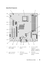
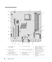
System Board Components 1 2 22 21 3 4 20 19 5 18 6 17 16 7 15 14 13 12 11 10 9 8 1 speaker connector (INT_SPKR) 4 power connector (PW_12V_A1) 2 processor socket (CPU) 5 SATA drive connectors (SATA2, SATA3) 3 memory module connectors (DIMM_1, DIMM_2, DIMM_3, DIMM_4) 6 SATA drive connectors (SATA0, SATA1) Quick Reference Guide 41
System Board Components 1 2 22 21 3 4 20 19 5 18 6 17 16 7 15 14 13 12 11 10 9 8 1 speaker connector (INT_SPKR) 4 power connector (PW_12V_A1) 2 processor socket (CPU) 5 SATA drive connectors (SATA2, SATA3) 3 memory module connectors (DIMM_1, DIMM_2, DIMM_3, DIMM_4) 6 SATA drive connectors (SATA0, SATA1) Quick Reference Guide 41
Quick Reference Guide
Page 45
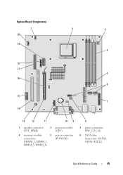
System Board Components 1 20 2 3 19 4 18 17 5 16 6 15 7 14 13 12 11 10 9 1 speaker connector (INT_SPKR) 2 processor socket (CPU) 4 memory module 5 power connector connectors (POWER1) (DIMM_1, DIMM_2, DIMM_3, DIMM_4) 8 3 power connector (PW_12V_A1) 6 SATA drive connectors (SATA0, SATA1, SATA2) Quick Reference Guide 45
System Board Components 1 20 2 3 19 4 18 17 5 16 6 15 7 14 13 12 11 10 9 1 speaker connector (INT_SPKR) 2 processor socket (CPU) 4 memory module 5 power connector connectors (POWER1) (DIMM_1, DIMM_2, DIMM_3, DIMM_4) 8 3 power connector (PW_12V_A1) 6 SATA drive connectors (SATA0, SATA1, SATA2) Quick Reference Guide 45
Quick Reference Guide
Page 49
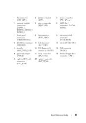
1 fan connector (FAN_CPU) 2 processor socket (CPU) 4 memory module 5 power connector connectors (POWER1) (DIMM_1, DIMM_2, DIMM_3, DIMM_4) 7 front-panel connector (FRONTPANEL) 8 fan connector (FAN_HDD) 10 CMOS reset jumper 11 battery ...
1 fan connector (FAN_CPU) 2 processor socket (CPU) 4 memory module 5 power connector connectors (POWER1) (DIMM_1, DIMM_2, DIMM_3, DIMM_4) 7 front-panel connector (FRONTPANEL) 8 fan connector (FAN_HDD) 10 CMOS reset jumper 11 battery ...
Quick Reference Guide
Page 56
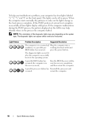
The diagnostic lights can be off Plug the computer into a condition, or a possible pre- press the power button. A possible processor failure has Reinstall the processor and occurred. The lights can appear either vertical or horizontal. The diagnostic lights are not lit after the computer successfully boots to the operating system. ...
The diagnostic lights can be off Plug the computer into a condition, or a possible pre- press the power button. A possible processor failure has Reinstall the processor and occurred. The lights can appear either vertical or horizontal. The diagnostic lights are not lit after the computer successfully boots to the operating system. ...

User's Guide
Page 4
Optical Drive 78 Processor 83 Removing the Processor 83 Installing the Processor 85 Power Supply 89 Replacing the Power Supply 89 DC Power Connectors 91 4 Desktop Computer 97 About Your Desktop Computer 97 Front View 97 Back ...
Optical Drive 78 Processor 83 Removing the Processor 83 Installing the Processor 85 Power Supply 89 Replacing the Power Supply 89 DC Power Connectors 91 4 Desktop Computer 97 About Your Desktop Computer 97 Front View 97 Back ...

User's Guide
Page 5
Processor 179 Removing the Processor 179 Installing the Processor 182 5 Small Form Factor Computer 185 About Your Small Form Factor Computer 185 Front View 185 Back View 186 Back-Panel Connectors 187 Inside Your ... Cards 223 PCI Express and DVI Cards 227 PS/2 Serial Port Adapters 233 Power Supply 237 Replacing the Power Supply 237 DC Power Connectors 239 Processor 243 Removing the Processor 243 Installing the Processor 245 Contents 5
Processor 179 Removing the Processor 179 Installing the Processor 182 5 Small Form Factor Computer 185 About Your Small Form Factor Computer 185 Front View 185 Back View 186 Back-Panel Connectors 187 Inside Your ... Cards 223 PCI Express and DVI Cards 227 PS/2 Serial Port Adapters 233 Power Supply 237 Replacing the Power Supply 237 DC Power Connectors 239 Processor 243 Removing the Processor 243 Installing the Processor 245 Contents 5
User's Guide
Page 16
... computer model. Contact information, service call status and support history, service contract, online discussions with other Dell customers • Upgrades - If you reinstall the operating system for Dell™ 3.5-inch USB floppy drives, AMD™ processors, optical drives, and USB devices. The software automatically detects your computer and operating system and installs the...
... computer model. Contact information, service call status and support history, service contract, online discussions with other Dell customers • Upgrades - If you reinstall the operating system for Dell™ 3.5-inch USB floppy drives, AMD™ processors, optical drives, and USB devices. The software automatically detects your computer and operating system and installs the...
User's Guide
Page 20
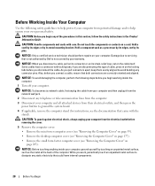
... disconnect a network cable, first unplug the cable from your computer and then unplug it from potential damage and to servicing that is not authorized by Dell is not covered by its metal mounting bracket. Do not touch the components or contacts on your computer. NOTICE: To avoid damaging the computer, perform... and all attached devices from the electrical outlet before you begin working inside your computer, ground yourself by touching an unpainted metal surface, such as a processor by its edges, not by its strain-relief loop, not on page 203).
... disconnect a network cable, first unplug the cable from your computer and then unplug it from potential damage and to servicing that is not authorized by Dell is not covered by its metal mounting bracket. Do not touch the components or contacts on your computer. NOTICE: To avoid damaging the computer, perform... and all attached devices from the electrical outlet before you begin working inside your computer, ground yourself by touching an unpainted metal surface, such as a processor by its edges, not by its strain-relief loop, not on page 203).
User's Guide
Page 31
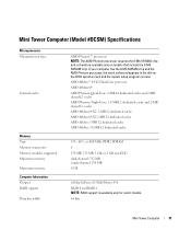
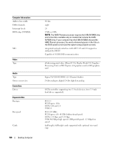
... only on the BIOS splash screen and the system setup program screens. If your computer has the 8-Mb NVRAM chip and the AMD Phenom processor, the word enhanced appears in the title on models that include the 8-Mb NVRAM chip. Mini Tower Computer (Model #DCSM) Specifications . ...Microprocessor Microprocessor type Internal cache AMD Phenom™ processors NOTE: The AMD Phenom processor requires the 8-Mb NVRAM chip and is available only for select models. 64 bits Mini Tower Computer 31
... only on the BIOS splash screen and the system setup program screens. If your computer has the 8-Mb NVRAM chip and the AMD Phenom processor, the word enhanced appears in the title on models that include the 8-Mb NVRAM chip. Mini Tower Computer (Model #DCSM) Specifications . ...Microprocessor Microprocessor type Internal cache AMD Phenom™ processors NOTE: The AMD Phenom processor requires the 8-Mb NVRAM chip and is available only for select models. 64 bits Mini Tower Computer 31
User's Guide
Page 32
If your computer has the 8-Mb NVRAM chip and the AMD Phenom processor, the word enhanced appears in the title on models that include the 8-Mb NVRAM chip. support for Atmel 1-Mb and 2-Mb EEPROM Capable of 10/... (NVRAM) NIC Video Type Audio Type Stereo conversion Controllers Drives Expansion Bus Bus type 40 bits eight 24 8 Mb or 4 Mb NOTE: The AMD Phenom processor requires the 8-Mb NVRAM chip and is therefore available only on the BIOS splash screen and the system setup program screens.
If your computer has the 8-Mb NVRAM chip and the AMD Phenom processor, the word enhanced appears in the title on models that include the 8-Mb NVRAM chip. support for Atmel 1-Mb and 2-Mb EEPROM Capable of 10/... (NVRAM) NIC Video Type Audio Type Stereo conversion Controllers Drives Expansion Bus Bus type 40 bits eight 24 8 Mb or 4 Mb NOTE: The AMD Phenom processor requires the 8-Mb NVRAM chip and is therefore available only on the BIOS splash screen and the system setup program screens.
User's Guide
Page 83
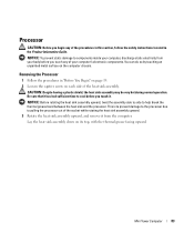
...touching an unpainted metal surface on its top, with the thermal grease facing upward. Be sure that it has had sufficient time to pulling the processor out of the procedures in this section, follow the safety instructions located in "Before You Begin" on page 19. 2 Loosen the captive ... Rotate the heat sink assembly upward, and remove it . This is to prevent damage to the processor due to cool before you touch it from the computer. Mini Tower Computer 83 Removing the Processor 1 Follow the procedures in the Product Information Guide. Lay the heat sink assembly down on the ...
...touching an unpainted metal surface on its top, with the thermal grease facing upward. Be sure that it has had sufficient time to pulling the processor out of the procedures in this section, follow the safety instructions located in "Before You Begin" on page 19. 2 Loosen the captive ... Rotate the heat sink assembly upward, and remove it . This is to prevent damage to the processor due to cool before you touch it from the computer. Mini Tower Computer 83 Removing the Processor 1 Follow the procedures in the Product Information Guide. Lay the heat sink assembly down on the ...
User's Guide
Page 84
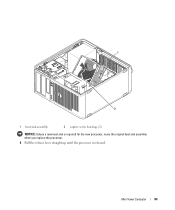
1 2 1 heat sink assembly 2 captive screw housings (2) NOTICE: Unless a new heat sink is required for the new processor, reuse the original heat sink assembly when you replace the processor. 4 Pull the release lever straight up until the processor is released. Mini Tower Computer 84
1 2 1 heat sink assembly 2 captive screw housings (2) NOTICE: Unless a new heat sink is required for the new processor, reuse the original heat sink assembly when you replace the processor. 4 Pull the release lever straight up until the processor is released. Mini Tower Computer 84
User's Guide
Page 85
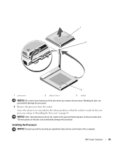
... the release position so that the socket is ready for the new processor and go to "Installing the Processor" on the processor pins. Mini Tower Computer 85 NOTICE: After removing the processor, be careful not to get any of the computer. Thermal grease on...the pins when you remove the processor. Bending the pins can permanently damage the processor. Installing the Processor NOTICE: Ground yourself by touching an unpainted metal surface on the pins can permanently damage the processor. 5 Remove the processor from the socket. 1 2 3 1 processor 2 release lever 3 socket NOTICE:...
... the release position so that the socket is ready for the new processor and go to "Installing the Processor" on the processor pins. Mini Tower Computer 85 NOTICE: After removing the processor, be careful not to get any of the computer. Thermal grease on...the pins when you remove the processor. Bending the pins can permanently damage the processor. Installing the Processor NOTICE: Ground yourself by touching an unpainted metal surface on the pins can permanently damage the processor. 5 Remove the processor from the socket. 1 2 3 1 processor 2 release lever 3 socket NOTICE:...
User's Guide
Page 86
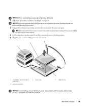
...fully extended, move it to bend any of the processor pins. NOTICE: Be careful not to that the processor aligns properly with the socket, and do not bend any of the processor and socket. 3 2 1 1 socket and processor pin-1 indicator 4 processor socket 2 processor 4 3 release lever NOTICE: To avoid damage, ...ensure that position. 4 Align the pin-1 corners of the pins when you install the processor. Bending the pins can permanently damage the processor. 2 Unpack the new processor, being careful not to bend any of the pins. 1 Follow the procedures in the socket to...
...fully extended, move it to bend any of the processor pins. NOTICE: Be careful not to that the processor aligns properly with the socket, and do not bend any of the processor and socket. 3 2 1 1 socket and processor pin-1 indicator 4 processor socket 2 processor 4 3 release lever NOTICE: To avoid damage, ...ensure that position. 4 Align the pin-1 corners of the pins when you install the processor. Bending the pins can permanently damage the processor. 2 Unpack the new processor, being careful not to bend any of the pins. 1 Follow the procedures in the socket to...
User's Guide
Page 87
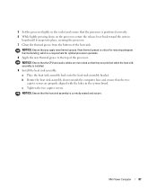
... grease. New thermal grease is critical for ensuring adequate thermal bonding, which is correctly seated and secure. 5 Set the processor lightly in the system board. NOTICE: Ensure that the processor is positioned correctly. 6 While lightly pressing down towards the computer base and ensure that the two captive screws are not ...routed so that the heat sink assembly is a requirement for optimal processor operation. 8 Apply the new thermal grease to the top of the heat sink. b Rotate the heat sink assembly down on the...
... grease. New thermal grease is critical for ensuring adequate thermal bonding, which is correctly seated and secure. 5 Set the processor lightly in the system board. NOTICE: Ensure that the processor is positioned correctly. 6 While lightly pressing down towards the computer base and ensure that the two captive screws are not ...routed so that the heat sink assembly is a requirement for optimal processor operation. 8 Apply the new thermal grease to the top of the heat sink. b Rotate the heat sink assembly down on the...
User's Guide
Page 102
System Board Components 1 21 20 19 18 17 16 15 14 2 3 DIMM 1 DIMM 2 DIMM 3 DIMM 4 4 SATA 2 5 6 SATA 1 SATA 0 7 13 12 11 10 9 8 1 speaker connector (INT_SPKR) 4 power connector (PW_12V_A1) 7 front-panel connector (FRONTPANEL) 10 battery socket (BATTERY) 2 processor socket (CPU) 3 memory module connectors (DIMM_1, DIMM_2, DIMM_3, DIMM_4) 5 power connector (POWER1) 6 SATA drive connectors (SATA0, SATA1, SATA2) 8 intrusion switch connector (INTRUDER) 9 CMOS reset jumper (RTCRST) 11 internal USB (USB1) 12 PCI Express x16 connector (SLOT1) 102 Desktop Computer
System Board Components 1 21 20 19 18 17 16 15 14 2 3 DIMM 1 DIMM 2 DIMM 3 DIMM 4 4 SATA 2 5 6 SATA 1 SATA 0 7 13 12 11 10 9 8 1 speaker connector (INT_SPKR) 4 power connector (PW_12V_A1) 7 front-panel connector (FRONTPANEL) 10 battery socket (BATTERY) 2 processor socket (CPU) 3 memory module connectors (DIMM_1, DIMM_2, DIMM_3, DIMM_4) 5 power connector (POWER1) 6 SATA drive connectors (SATA0, SATA1, SATA2) 8 intrusion switch connector (INTRUDER) 9 CMOS reset jumper (RTCRST) 11 internal USB (USB1) 12 PCI Express x16 connector (SLOT1) 102 Desktop Computer

User's Guide
Page 105
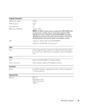
... RAID 1 NOTE: RAID support is therefore available only on select models. 64 bits Desktop Computer 105 AMD Athlon™ 64 X2 Dual-Core processor AMD Athlon 64 AMD Phenom Quad-Core: 2-MB L2 dedicated cache and 2-MB shared L3 cache AMD Phenom Triple-Core: 1.5-MB L2 dedicated ... Type Memory connectors Memory modules supported Minimum memory Maximum memory Computer Information Chipset RAID support Data bus width AMD Phenom™ processors NOTE: The AMD Phenom processor requires the 8-Mb NVRAM chip and is available only on models that include the 8-Mb NVRAM chip. If your computer has...
... RAID 1 NOTE: RAID support is therefore available only on select models. 64 bits Desktop Computer 105 AMD Athlon™ 64 X2 Dual-Core processor AMD Athlon 64 AMD Phenom Quad-Core: 2-MB L2 dedicated cache and 2-MB shared L3 cache AMD Phenom Triple-Core: 1.5-MB L2 dedicated ... Type Memory connectors Memory modules supported Minimum memory Maximum memory Computer Information Chipset RAID support Data bus width AMD Phenom™ processors NOTE: The AMD Phenom processor requires the 8-Mb NVRAM chip and is available only on models that include the 8-Mb NVRAM chip. If your computer has...
User's Guide
Page 106
If your computer has the 8-Mb NVRAM chip and the AMD Phenom processor, the word enhanced appears in the title on models that include the 8-Mb NVRAM chip. integrated network interface with ASF 1.03 and 2.0 support as defined ... Stereo conversion Controllers Drives Expansion Bus Bus type Bus speed Cards 106 Desktop Computer 40 bits eight 24 8 Mb or 4 Mb NOTE: The AMD Phenom processor requires the 8-Mb NVRAM chip and is therefore available only on the BIOS splash screen and the system setup program screens.
If your computer has the 8-Mb NVRAM chip and the AMD Phenom processor, the word enhanced appears in the title on models that include the 8-Mb NVRAM chip. integrated network interface with ASF 1.03 and 2.0 support as defined ... Stereo conversion Controllers Drives Expansion Bus Bus type Bus speed Cards 106 Desktop Computer 40 bits eight 24 8 Mb or 4 Mb NOTE: The AMD Phenom processor requires the 8-Mb NVRAM chip and is therefore available only on the BIOS splash screen and the system setup program screens.


