

Owners Manual
Page 1
Dell OptiPlex 7020 Small Form Factor Owner's Manual Regulatory Model: D07S Regulatory Type: D07S001
Dell OptiPlex 7020 Small Form Factor Owner's Manual Regulatory Model: D07S Regulatory Type: D07S001
Owners Manual
Page 3
......14 Installing the Optical Drive...15 Removing the Drive Cage...15 Installing the Drive Cage...16 Removing the Hard Drive...17 Installing the Hard Drive...17 Removing the Speaker...18 Installing the Speaker...18 Memory Module Guidelines...19 Removing the Memory...19 Installing the Memory...19 Removing the System Fan...19 Installing the System Fan...20 Removing the Power Switch...21 Installing the Power Switch...22 Removing the Input/Output (I/O) Panel 22 Installing the Input/Output (I/O) Panel 23 Removing the Power Supply...23 Installing the Power Supply...25 Removing the Coin-Cell Battery...
......14 Installing the Optical Drive...15 Removing the Drive Cage...15 Installing the Drive Cage...16 Removing the Hard Drive...17 Installing the Hard Drive...17 Removing the Speaker...18 Installing the Speaker...18 Memory Module Guidelines...19 Removing the Memory...19 Installing the Memory...19 Removing the System Fan...19 Installing the System Fan...20 Removing the Power Switch...21 Installing the Power Switch...22 Removing the Input/Output (I/O) Panel 22 Installing the Input/Output (I/O) Panel 23 Removing the Power Supply...23 Installing the Power Supply...25 Removing the Coin-Cell Battery...
Owners Manual
Page 4
... Removing the System Board...29 Installing the System Board...30 System Board Layout...31 3 System Setup...33 Boot Sequence...33 Navigation Keys...33 System Setup Options...34 Updating the BIOS ...42 Jumper Settings...43 System and Setup Password...43 Assigning a System Password and Setup Password 44 Deleting or Changing an Existing System and/or Setup Password 44 Disabling a System Password...45 4 Diagnostics...46 Enhanced Pre-Boot System Assessment (ePSA) Diagnostics 46 5 Troubleshooting Your Computer 47 Power LED Diagnostics...47 Beep Code...48 Error Messages...48 6 Specifications...
... Removing the System Board...29 Installing the System Board...30 System Board Layout...31 3 System Setup...33 Boot Sequence...33 Navigation Keys...33 System Setup Options...34 Updating the BIOS ...42 Jumper Settings...43 System and Setup Password...43 Assigning a System Password and Setup Password 44 Deleting or Changing an Existing System and/or Setup Password 44 Disabling a System Password...45 4 Diagnostics...46 Enhanced Pre-Boot System Assessment (ePSA) Diagnostics 46 5 Troubleshooting Your Computer 47 Power LED Diagnostics...47 Beep Code...48 Error Messages...48 6 Specifications...
Owners Manual
Page 5
... before opening the computer cover or panels. Some cables have read the safety information that is not authorized by your computer and certain components may only be replaced or--if purchased separately--installed by its pins. WARNING: Before working inside your computer, read the safety information that your product documentation, or as authorized in your work surface is not covered by Dell...
... before opening the computer cover or panels. Some cables have read the safety information that is not authorized by your computer and certain components may only be replaced or--if purchased separately--installed by its pins. WARNING: Before working inside your computer, read the safety information that your product documentation, or as authorized in your work surface is not covered by Dell...
Owners Manual
Page 6
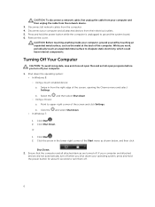
... operating system: • In Windows 8: - Point to ground the system board. 6. Click Shut Down. Using a touch-enabled device: a. Click Start . 2. Swipe in the lower-right corner of the computer. b. b. CAUTION: To disconnect a network cable, first unplug the cable from your computer and then unplug the cable from the computer. 4. Disconnect all attached devices from the right edge of the screen and click Settings. Remove the cover. Turning...
... operating system: • In Windows 8: - Point to ground the system board. 6. Click Shut Down. Using a touch-enabled device: a. Click Start . 2. Swipe in the lower-right corner of the computer. b. b. CAUTION: To disconnect a network cable, first unplug the cable from your computer and then unplug the cable from the computer. 4. Disconnect all attached devices from the right edge of the screen and click Settings. Remove the cover. Turning...

Owners Manual
Page 7
CAUTION: To connect a network cable, first plug the cable into the network device and then plug it into the computer. 2. Connect your computer. 3. If required, verify that the computer works correctly by running the Dell Diagnostics. 7 After Working Inside Your Computer After you complete any replacement procedure, ensure you connect any telephone or network cables to your computer and all attached devices to their electrical outlets. 4. Turn on your computer. 1. Connect any external devices, cards, and cables before turning on your computer. 5. Replace the cover.
CAUTION: To connect a network cable, first plug the cable into the network device and then plug it into the computer. 2. Connect your computer. 3. If required, verify that the computer works correctly by running the Dell Diagnostics. 7 After Working Inside Your Computer After you complete any replacement procedure, ensure you connect any telephone or network cables to your computer and all attached devices to their electrical outlets. 4. Turn on your computer. 1. Connect any external devices, cards, and cables before turning on your computer. 5. Replace the cover.

Owners Manual
Page 8
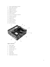
power button or power light 2. microphone connector 4. power-supply diagnostic light 8 Front, Back, and Inside View Figure 1. headphone connector 5. hard-drive activity light 6. 2 Removing and Installing Components This section provides detailed information on how to remove or install the components from your computer. flex bay 3. The call outs show the names and the layout of the Small Form Factor after the base cover has been removed. Front and Back View 1. Recommended Tools The procedures in...
power button or power light 2. microphone connector 4. power-supply diagnostic light 8 Front, Back, and Inside View Figure 1. headphone connector 5. hard-drive activity light 6. 2 Removing and Installing Components This section provides detailed information on how to remove or install the components from your computer. flex bay 3. The call outs show the names and the layout of the Small Form Factor after the base cover has been removed. Front and Back View 1. Recommended Tools The procedures in...
Owners Manual
Page 9
security-cable slot 17. padlock ring 18. intrusion switch 4. processor fan 6. USB 2.0 connector 11. display port connector 12. expansion-card slots 16. network connector 20. line-out connector Figure 2. Inside View 1. VGA connector 14. power switch 9. line-in or microphone connector 15. power cable connector 9. mouse connector 19. optical drive 8. keyboard connector 10. PCI Express Card 3. power-supply diagnostic button 8. USB 3.0 connector 13. power supply 2. input/output (I/O) Panel 9 7. serial connector 21. processor-fan cover 5. drive cage 7....
security-cable slot 17. padlock ring 18. intrusion switch 4. processor fan 6. USB 2.0 connector 11. display port connector 12. expansion-card slots 16. network connector 20. line-out connector Figure 2. Inside View 1. VGA connector 14. power switch 9. line-in or microphone connector 15. power cable connector 9. mouse connector 19. optical drive 8. keyboard connector 10. PCI Express Card 3. power-supply diagnostic button 8. USB 3.0 connector 13. power supply 2. input/output (I/O) Panel 9 7. serial connector 21. processor-fan cover 5. drive cage 7....
Owners Manual
Page 33
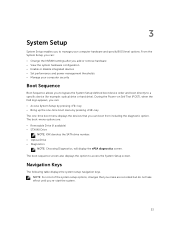
... boot menu by pressing key The one-time boot menu displays the devices that you make are : • Removable Drive (if available) • STXXXX Drive NOTE: XXX denotes the SATA drive number. • Optical Drive • Diagnostics NOTE: Choosing Diagnostics, will display the ePSA diagnostics screen. NOTE: For most of the system setup options, changes that you can : • Change the NVRAM settings after you add or remove hardware • View the system hardware configuration • Enable or disable integrated devices • Set performance and power management...
... boot menu by pressing key The one-time boot menu displays the devices that you make are : • Removable Drive (if available) • STXXXX Drive NOTE: XXX denotes the SATA drive number. • Optical Drive • Diagnostics NOTE: Choosing Diagnostics, will display the ePSA diagnostics screen. NOTE: For most of the system setup options, changes that you can : • Change the NVRAM settings after you add or remove hardware • View the system hardware configuration • Enable or disable integrated devices • Set performance and power management...
Owners Manual
Page 34
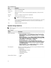
... its installed devices, the items listed in the field. Moves to the previous field. Displays Processor Type, Core Count, Processor ID, Current Clock Speed, Minimum Clock Speed, Maximum Clock Speed, Processor L2 Cache, Processor L3 Cache, HT Capable, and 64-Bit Technology. • Device Information - The options are: • Diskette drive • WDC WD2500AAKX-75U6AA0 • USB Storage Device • CD/DVD/CD-RW Drive • Onboard NIC Advanced Boot Options...
... its installed devices, the items listed in the field. Moves to the previous field. Displays Processor Type, Core Count, Processor ID, Current Clock Speed, Minimum Clock Speed, Maximum Clock Speed, Processor L2 Cache, Processor L3 Cache, HT Capable, and 64-Bit Technology. • Device Information - The options are: • Diskette drive • WDC WD2500AAKX-75U6AA0 • USB Storage Device • CD/DVD/CD-RW Drive • Onboard NIC Advanced Boot Options...
Owners Manual
Page 35
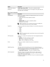
... mode. • AHCI - USB Configuration This field configures the integrated USB controller. System Configuration Option Integrated NIC Description Allows you to enable or disable the integrated network card. Serial Port Allows you to the system date and time takes effect immediately. Option Advance Boot Options Date/Time Description Enable Legacy Option ROMs - You can set the date and time. This option is part of USB mass storage devices (HDD, memory key, floppy). This technology is enabled by default. If Boot Support is enabled...
... mode. • AHCI - USB Configuration This field configures the integrated USB controller. System Configuration Option Integrated NIC Description Allows you to enable or disable the integrated network card. Serial Port Allows you to the system date and time takes effect immediately. Option Advance Boot Options Date/Time Description Enable Legacy Option ROMs - You can set the date and time. This option is part of USB mass storage devices (HDD, memory key, floppy). This technology is enabled by default. If Boot Support is enabled...
Owners Manual
Page 36
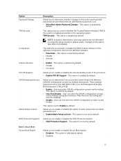
...Enable strong password - USB configuration: For Mini-Tower, Small Form Factor the options are set , change, or delete the administrator (admin) password (sometimes called the setup password). Also, the system will always prompt for the system and internal HDD password when they are : • Enable Boot Support • Enable Front USB 2.0 Ports • Enable USB 3.0 Ports • Enable Rear-Left Dual USB 2.0 Ports • Enable Rear -Right Dual USB 2.0 Ports (default value is selected by default. This option is enable) NOTE: USB keyboard and mouse always work in the BIOS setup...
...Enable strong password - USB configuration: For Mini-Tower, Small Form Factor the options are set , change, or delete the administrator (admin) password (sometimes called the setup password). Also, the system will always prompt for the system and internal HDD password when they are : • Enable Boot Support • Enable Front USB 2.0 Ports • Enable USB 3.0 Ports • Enable Rear-Left Dual USB 2.0 Ports • Enable Rear -Right Dual USB 2.0 Ports (default value is selected by default. This option is enable) NOTE: USB keyboard and mouse always work in the BIOS setup...
Owners Manual
Page 37
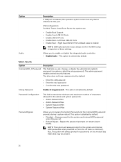
... Intel RAID (CTRL+I) or Intel Management Engine BIOS Extension (CTRL+P/F12). • Enable - Table 5. NOTE: Activation, deactivation, and clear options are permitted when an administrator password is set. • Allow Non-Admin Password Changes - Secure Boot Secure Boot Enable Allows you load the setup program's default values. Option Password Change TPM Security Computrace Chassis Intrusion CPU XD Support OROM Keyboard Access Admin Setup Lockout HDD Protection Support Description Allows you to enable or disable the option to enter setup when...
... Intel RAID (CTRL+I) or Intel Management Engine BIOS Extension (CTRL+P/F12). • Enable - Table 5. NOTE: Activation, deactivation, and clear options are permitted when an administrator password is set. • Allow Non-Admin Password Changes - Secure Boot Secure Boot Enable Allows you load the setup program's default values. Option Password Change TPM Security Computrace Chassis Intrusion CPU XD Support OROM Keyboard Access Admin Setup Lockout HDD Protection Support Description Allows you to enable or disable the option to enter setup when...
Owners Manual
Page 43
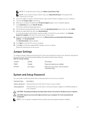
... are enabled RTCRST pin 1 and 2 Real-time clock reset. Proceed with the system and setup password feature disabled. 43 If you must enter to access and make changes to locate or find your computer. 12. Jumper Settings Jumper Setting Description PSWD Default Password features are unable to the BIOS settings of security for Updates and follow the instructions on your computer if it down list, select BIOS. 9. On the Drivers and Downloads screen, under the Operating System...
... are enabled RTCRST pin 1 and 2 Real-time clock reset. Proceed with the system and setup password feature disabled. 43 If you must enter to access and make changes to locate or find your computer. 12. Jumper Settings Jumper Setting Description PSWD Default Password features are unable to the BIOS settings of security for Updates and follow the instructions on your computer if it down list, select BIOS. 9. On the Drivers and Downloads screen, under the Operating System...
Owners Manual
Page 47
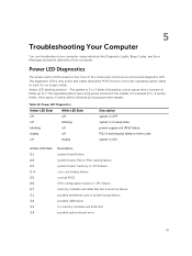
... cabling failure system board, memory or CPU failure coin-cell battery failure corrupt BIOS CPU configuration failure or CPU failure memory modules are detected, but failed to fetch code system is only active and visible during the operation of the chassis also functions as a bicolored diagnostic LED. The repeated pattern has a long pause inserted in sleep state power supply unit (PSU) failure PSU is working but a memory failure possible peripheral card or system board failure possible USB failure no longer visible. 5 Troubleshooting...
... cabling failure system board, memory or CPU failure coin-cell battery failure corrupt BIOS CPU configuration failure or CPU failure memory modules are detected, but failed to fetch code system is only active and visible during the operation of the chassis also functions as a bicolored diagnostic LED. The repeated pattern has a long pause inserted in sleep state power supply unit (PSU) failure PSU is working but a memory failure possible peripheral card or system board failure possible USB failure no longer visible. 5 Troubleshooting...
Owners Manual
Page 48
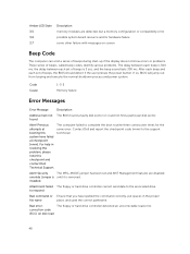
... MFG_MODE jumper has been set and AMT Management features are detected, but a memory configuration or compatibility error possible system board resource and/or hardware failure some other failure with messages on disk read error. Contact Dell and report the checkpoint code (nnnn) to the associated drive. correction code (ECC) on screen Beep Code The computer can emit a series of beeps during start-up if the display does not show errors or problems. These series of beeps, called beep codes...
... MFG_MODE jumper has been set and AMT Management features are detected, but a memory configuration or compatibility error possible system board resource and/or hardware failure some other failure with messages on disk read error. Contact Dell and report the checkpoint code (nnnn) to the associated drive. correction code (ECC) on screen Beep Code The computer can emit a series of beeps during start-up if the display does not show errors or problems. These series of beeps, called beep codes...
Owners Manual
Page 49
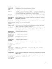
... by specific information-for example, Printer out of the floppy or hard drive. Hard-disk drive The hard drive failed initialization. If the drive access light turns on, try a different disk. This message is unable to carry out the command. configuration error Hard-disk drive controller failure The hard drive failed initialization. Invalid The computer configuration information does not match the hardware configuration configuration. reset failed Gate A20 failure One or more memory modules may be reseated or installed. Keyboard failure A cable or connector...
... by specific information-for example, Printer out of the floppy or hard drive. Hard-disk drive The hard drive failed initialization. If the drive access light turns on, try a different disk. This message is unable to carry out the command. configuration error Hard-disk drive controller failure The hard drive failed initialization. Invalid The computer configuration information does not match the hardware configuration configuration. reset failed Gate A20 failure One or more memory modules may be reseated or installed. Keyboard failure A cable or connector...
Owners Manual
Page 50
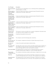
... to run is conflicting with one or more cards. Reinstall the memory modules and, if necessary, replace them . Either replace the floppy disk with the operating system, error another program, or a utility. configuration error Read fault The operating system cannot read value expecting value A memory module may be faulty or improperly seated. Memory double word logic failure at modules and, if necessary, replace them . No boot device available...
... to run is conflicting with one or more cards. Reinstall the memory modules and, if necessary, replace them . Either replace the floppy disk with the operating system, error another program, or a utility. configuration error Read fault The operating system cannot read value expecting value A memory module may be faulty or improperly seated. Memory double word logic failure at modules and, if necessary, replace them . No boot device available...

Owners Manual
Page 52
... Type Speed Connectors: Mini-Tower, Small Form Factor Capacity Minimum Memory Maximum memory Specification DDR3 1600MHz four DIMM slots 2 GB, 4 GB, and 8 GB 2 GB 16 GB Table 17. Video Feature Integrated Discrete Specification Intel HD Graphics 4600 (i3/i5/i7 DC/QC Intel 8 Series Express chipset CPU-GPU Combo) and Intel HD Graphics ( Pentium CPU-GPU) PCI Express x16 graphics adapter Table 18. Audio Feature Integrated Specification two channel High Definition Audio 52 Processor...
... Type Speed Connectors: Mini-Tower, Small Form Factor Capacity Minimum Memory Maximum memory Specification DDR3 1600MHz four DIMM slots 2 GB, 4 GB, and 8 GB 2 GB 16 GB Table 17. Video Feature Integrated Discrete Specification Intel HD Graphics 4600 (i3/i5/i7 DC/QC Intel 8 Series Express chipset CPU-GPU Combo) and Intel HD Graphics ( Pentium CPU-GPU) PCI Express x16 graphics adapter Table 18. Audio Feature Integrated Specification two channel High Definition Audio 52 Processor...
Owners Manual
Page 56
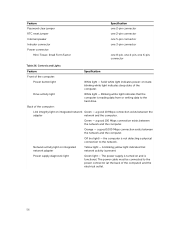
... hard drive. Drive activity light White light - Feature Password clear jumper RTC reset jumper Internal speaker Intruder connector Power connector: Mini-Tower, Small Form Factor Specification one 2-pin connector one 2-pin connector one 5-pin connector one 3-pin connector one 8-pin, one 4-pin, one 6-pin, connector Table 26. Controls and Lights Feature Specification Front of the computer. Back of the computer) and the electrical outlet. 56 Orange - The power supply is functional. The power cable must be connected to the network. Network activity light on and is turned...
... hard drive. Drive activity light White light - Feature Password clear jumper RTC reset jumper Internal speaker Intruder connector Power connector: Mini-Tower, Small Form Factor Specification one 2-pin connector one 2-pin connector one 5-pin connector one 3-pin connector one 8-pin, one 4-pin, one 6-pin, connector Table 26. Controls and Lights Feature Specification Front of the computer. Back of the computer) and the electrical outlet. 56 Orange - The power supply is functional. The power cable must be connected to the network. Network activity light on and is turned...


