User Manual
Page 1
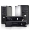
.... Front and Back View Figure 1. power supply diagnostic light Regulatory Model: D05D, D09M, D03S, D01U Regulatory Type: D05D002, D09M003, D03S002, D01U003 2011 - 12 headphone connector 4. USB 3.0 connectors (2) 9. Dell OptiPlex 7010 Setup and Features Information About Warnings WARNING: A WARNING indicates a potential for property damage, personal injury, or death. Mini-Tower -
.... Front and Back View Figure 1. power supply diagnostic light Regulatory Model: D05D, D09M, D03S, D01U Regulatory Type: D05D002, D09M003, D03S002, D01U003 2011 - 12 headphone connector 4. USB 3.0 connectors (2) 9. Dell OptiPlex 7010 Setup and Features Information About Warnings WARNING: A WARNING indicates a potential for property damage, personal injury, or death. Mini-Tower -
User Manual
Page 2
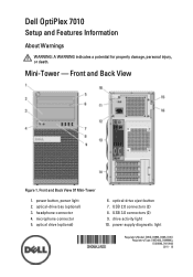
... light 9. expansion-card slots (4) 14. power connector 13. security-cable slot 16. microphone connector 7. back panel connectors 13. power supply diagnostic light 2 padlock ring Desktop - USB 3.0 connectors (2) 6. Front and Back View Figure 2. headphone connector 8. security-cable slot 11. power connector 12. power button, power light 4. padlock ring 10. power supply diagnostic...
... light 9. expansion-card slots (4) 14. power connector 13. security-cable slot 16. microphone connector 7. back panel connectors 13. power supply diagnostic light 2 padlock ring Desktop - USB 3.0 connectors (2) 6. Front and Back View Figure 2. headphone connector 8. security-cable slot 11. power connector 12. power button, power light 4. padlock ring 10. power supply diagnostic...
User Manual
Page 3
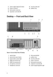
mouse connector 2. serial connector 7. keyboard connector 9. USB 2.0 connectors (2) 10. network connector 4. line-in/microphone connector 3 line-out connector 8. VGA connector 13. power supply diagnostic button Mini-Tower and Desktop - network link integrity light 3. network activity light 5. DisplayPort connectors (2) 11. USB 3.0 connectors (2) 12. Back Panel View of Mini-Tower And Desktop 1. USB 2.0 connectors (2) 6. 15. Back Panel View Figure 3.
mouse connector 2. serial connector 7. keyboard connector 9. USB 2.0 connectors (2) 10. network connector 4. line-in/microphone connector 3 line-out connector 8. VGA connector 13. power supply diagnostic button Mini-Tower and Desktop - network link integrity light 3. network activity light 5. DisplayPort connectors (2) 11. USB 3.0 connectors (2) 12. Back Panel View of Mini-Tower And Desktop 1. USB 2.0 connectors (2) 6. 15. Back Panel View Figure 3.

User Manual
Page 4
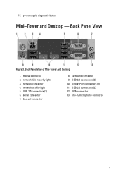
USB 3.0 connectors (2) 6. headphone connector 8. padlock ring 10. power supply diagnostic button 13. back panel connectors 15. optical drive 2. power button, power light 4. optical-drive eject button 3. security-cable slot 11. power supply diagnostic light 14. microphone connector 7. expansion-card slots (2) 4 USB 2.0 connectors (2) 5. Front and Back View Of Small Form Factor 1. Small Form Factor - Front and Back View Figure 4. drive activity light 9. power connector 12.
USB 3.0 connectors (2) 6. headphone connector 8. padlock ring 10. power supply diagnostic button 13. back panel connectors 15. optical drive 2. power button, power light 4. optical-drive eject button 3. security-cable slot 11. power supply diagnostic light 14. microphone connector 7. expansion-card slots (2) 4 USB 2.0 connectors (2) 5. Front and Back View Of Small Form Factor 1. Small Form Factor - Front and Back View Figure 4. drive activity light 9. power connector 12.

User Manual
Page 5
mouse connector 2. serial connector 3. network activity light 6. USB 3.0 connectors (2) 13. USB 2.0 connectors (2) 12. link integrity light 4. VGA connector 10. Small Form Factor - Back Panel View Figure 5. Back Panel View Of Small Form Factor 1. line-out connector 8. USB 2.0 connectors (2) 7. line-in/microphone connector 5 keyboard connector 9. DisplayPort connectors (2) 11. network connector 5.
mouse connector 2. serial connector 3. network activity light 6. USB 3.0 connectors (2) 13. USB 2.0 connectors (2) 12. link integrity light 4. VGA connector 10. Small Form Factor - Back Panel View Figure 5. Back Panel View Of Small Form Factor 1. line-out connector 8. USB 2.0 connectors (2) 7. line-in/microphone connector 5 keyboard connector 9. DisplayPort connectors (2) 11. network connector 5.

User Manual
Page 6
... button, power light 4. microphone connector 7. security-cable slot 13. Wi-Fi antenna (optional) 9. Ultra Small Form Factor - line-in/microphone connector 16. VGA connector 17. USB 3.0 connectors (2) 20. optical drive 2. drive activity light 5. network activity light 10. DisplayPort connectors (2) 18. serial connector 19. link integrity light 6 captive thumbscrew 11. headphone connector...
... button, power light 4. microphone connector 7. security-cable slot 13. Wi-Fi antenna (optional) 9. Ultra Small Form Factor - line-in/microphone connector 16. VGA connector 17. USB 3.0 connectors (2) 20. optical drive 2. drive activity light 5. network activity light 10. DisplayPort connectors (2) 18. serial connector 19. link integrity light 6 captive thumbscrew 11. headphone connector...
User Manual
Page 7
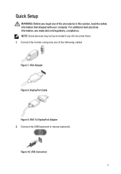
NOTE: Some devices may not be included if you begin any of the following cables: Figure 7. VGA To DisplayPort Adapter 2. Figure 10. VGA Adapter Figure 8. Connect the monitor using only one of the procedures in this section, read the safety information that shipped with your computer. USB Connection 7 DisplayPort Cable Figure 9. Connect the USB keyboard or mouse (optional). For additional best practices information, see www.dell.com/regulatory_compliance. Quick Setup WARNING: Before you did not order them. 1.
NOTE: Some devices may not be included if you begin any of the following cables: Figure 7. VGA To DisplayPort Adapter 2. Figure 10. VGA Adapter Figure 8. Connect the monitor using only one of the procedures in this section, read the safety information that shipped with your computer. USB Connection 7 DisplayPort Cable Figure 9. Connect the USB keyboard or mouse (optional). For additional best practices information, see www.dell.com/regulatory_compliance. Quick Setup WARNING: Before you did not order them. 1.
Owner's Manual (Desktop)
Page 33
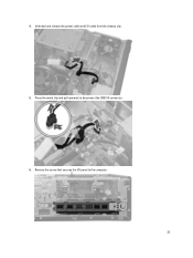
Remove the screw that secures the I /O cable from the chassis clip. 5. Unthread and release the power cable and I /O panel to disconnect the USB 3.0 connector. 6. Press the metal clip and pull upwards to the computer. 33 4.
Remove the screw that secures the I /O cable from the chassis clip. 5. Unthread and release the power cable and I /O panel to disconnect the USB 3.0 connector. 6. Press the metal clip and pull upwards to the computer. 33 4.
Owner's Manual (Desktop)
Page 36
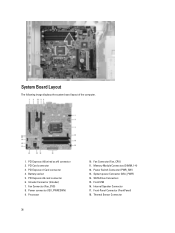
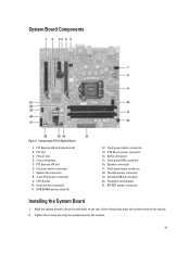
Intruder Connector (Intruder) 7. Processor 36 10. System power Connector (Mini_PWR) 14. Front USB 16. Internal Speaker Connector 17. Thermal Sensor Connector PCI Express x16 (wired as x4) connector 2. PCI Express x16 card connector 6. Battery socket 5. Fan Connector (Fan_CPU) ...
Intruder Connector (Intruder) 7. Processor 36 10. System power Connector (Mini_PWR) 14. Front USB 16. Internal Speaker Connector 17. Thermal Sensor Connector PCI Express x16 (wired as x4) connector 2. PCI Express x16 card connector 6. Battery socket 5. Fan Connector (Fan_CPU) ...
Owner's Manual (Desktop)
Page 37
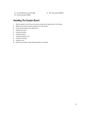
Internal USB Connector (INT_USB) 20. Tighten the screws securing the system board to the system board. 4. Install the expansion card. 8. Password Jumper (PSWD) 21. Connect all the cables to the chassis. 3. Install the memory. 7. Install the cover. 10. Follow the procedures in the chassis. 2. Align the system board to the port connectors and place the system board in After Working Inside Your Computer. 37 19. Install the processor. 5. Install the front bezel. 9. RTC reset jumper (RTCRST) Installing The System Board 1. Install the heat sink. 6.
Internal USB Connector (INT_USB) 20. Tighten the screws securing the system board to the system board. 4. Install the expansion card. 8. Password Jumper (PSWD) 21. Connect all the cables to the chassis. 3. Install the memory. 7. Install the cover. 10. Follow the procedures in the chassis. 2. Align the system board to the port connectors and place the system board in After Working Inside Your Computer. 37 19. Install the processor. 5. Install the front bezel. 9. RTC reset jumper (RTCRST) Installing The System Board 1. Install the heat sink. 6.
Owner's Manual (Desktop)
Page 40
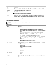
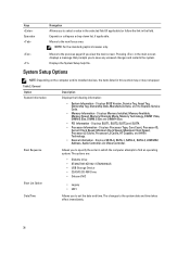
... information: • System Information - Boot Sequence Allows you to set the date and time. The options are: • Diskette drive • ST320LT007-9ZV142 / ST3250312AS • USB Storage Device • CD/DVD/CD-RW Drive • Onboard NIC Boot List Option • Legacy • UEFI Date/Time Allows you to select a value...
... information: • System Information - Boot Sequence Allows you to set the date and time. The options are: • Diskette drive • ST320LT007-9ZV142 / ST3250312AS • USB Storage Device • CD/DVD/CD-RW Drive • Onboard NIC Boot List Option • Legacy • UEFI Date/Time Allows you to select a value...
Owner's Manual (Desktop)
Page 41
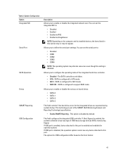
... - This technology is configured for AHCI mode. • RAID ON - System Configuration Option Integrated NIC Serial Port SATA Operation Drives SMART Reporting USB Configuration Description Allows you to : • Disabled • COM1 • COM2 • COM3 • COM4 NOTE: The operating system ... items listed in this section may or may allocate resources even though the setting is disabled. This field configures the integrated USB controller. You can set the integrated NIC to configure the operating mode of the SMART (Self Monitoring Analysis and Reporting Technology...
... - This technology is configured for AHCI mode. • RAID ON - System Configuration Option Integrated NIC Serial Port SATA Operation Drives SMART Reporting USB Configuration Description Allows you to : • Disabled • COM1 • COM2 • COM3 • COM4 NOTE: The operating system ... items listed in this section may or may allocate resources even though the setting is disabled. This field configures the integrated USB controller. You can set the integrated NIC to configure the operating mode of the SMART (Self Monitoring Analysis and Reporting Technology...
Owner's Manual (Desktop)
Page 42
...Description For Mini-Tower, Desktop, Small Form Factor the options are: • Enable Boot Support • Enable Rear Dual USB Ports • Enable Rear Quad USB Ports • Enable Front USB Ports For Ultra Small Form Factor, the options are: • Enable Boot Support • Enable Rear Dual... USB 2.0 Ports • Enable Rear Dual USB 3.0 Ports • Enable Front USB Ports NOTE: USB keyboard and mouse always work in the BIOS setup irrespective of characters allowed for the admin and system ...
...Description For Mini-Tower, Desktop, Small Form Factor the options are: • Enable Boot Support • Enable Rear Dual USB Ports • Enable Rear Quad USB Ports • Enable Front USB Ports For Ultra Small Form Factor, the options are: • Enable Boot Support • Enable Rear Dual... USB 2.0 Ports • Enable Rear Dual USB 3.0 Ports • Enable Front USB Ports NOTE: USB keyboard and mouse always work in the BIOS setup irrespective of characters allowed for the admin and system ...
Owner's Manual (Desktop)
Page 45
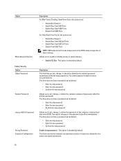
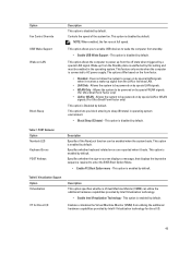
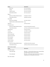
...Form Factor only) • LAN or WLAN - Allows the system to wake the computer from standby. • Enable USB Wake Support - This option lets you to enable USB devices to be powered on by default. POST Behavior Option Numlock LED Keyboard Errors POST Hotkeys Description Specifies if the NumLock... the LAN or wireless LAN. • LAN Only - Does not allow the system to AC power supply. Option Fan Control Override USB Wake Support Wake on LAN Block Sleep Description This option is disabled by Intel Virtualization technology. • Enable Intel Virtualization Technology -
...Form Factor only) • LAN or WLAN - Allows the system to wake the computer from standby. • Enable USB Wake Support - This option lets you to enable USB devices to be powered on by default. POST Behavior Option Numlock LED Keyboard Errors POST Hotkeys Description Specifies if the NumLock... the LAN or wireless LAN. • LAN Only - Does not allow the system to AC power supply. Option Fan Control Override USB Wake Support Wake on LAN Block Sleep Description This option is disabled by Intel Virtualization technology. • Enable Intel Virtualization Technology -

Owner's Manual (Desktop)
Page 53
... battery failure corrupt BIOS CPU configuration failure or CPU failure memory modules are detected, but a memory failure possible peripheral card or system board failure possible USB failure no longer visible. Once the operating system starts to fetch code off steady system is only active and visible during the operation of the...
... battery failure corrupt BIOS CPU configuration failure or CPU failure memory modules are detected, but a memory failure possible peripheral card or system board failure possible USB failure no longer visible. Once the operating system starts to fetch code off steady system is only active and visible during the operation of the...
Owner's Manual (Desktop)
Page 58
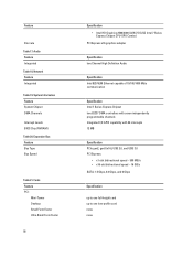
... 7 Series Express Chipset two 82C37 DMA controllers with seven independently programmable channels Integrated I/O APIC capability with 24 interrupts 12 MB Specification PCIe gen2, gen3 (x16), USB 2.0, and USB 3.0 PCI Express: • x1-slot bidirectional speed - 500 MB/s • x16-slot bidirectional speed - 16 GB/s SATA: 1.5 Gbps, 3.0 Gbps, and 6 Gbps Specification up to...
... 7 Series Express Chipset two 82C37 DMA controllers with seven independently programmable channels Integrated I/O APIC capability with 24 interrupts 12 MB Specification PCIe gen2, gen3 (x16), USB 2.0, and USB 3.0 PCI Express: • x1-slot bidirectional speed - 500 MB/s • x16-slot bidirectional speed - 16 GB/s SATA: 1.5 Gbps, 3.0 Gbps, and 6 Gbps Specification up to...

Owner's Manual (Desktop)
Page 60
...-Tower, Desktop, Small Form Factor Ultra Small Form Factor USB 3.0: Video Specification one RJ45 connector one 9-pin connector; 16550 C compatible one 120-pin connector Small Form Factor and Ultra Small Form Factor none PCI Express ... connector • two 20-pin DisplayPort connectors NOTE: Available video connectors may vary based on the graphics card selected. one PCI Express lane and one USB interface: Mini-Tower, Desktop, Small Form Factor none Ultra Small Form Factor one 36-pin connector Small Form Factor and Ultra Small Form Factor none...
...-Tower, Desktop, Small Form Factor Ultra Small Form Factor USB 3.0: Video Specification one RJ45 connector one 9-pin connector; 16550 C compatible one 120-pin connector Small Form Factor and Ultra Small Form Factor none PCI Express ... connector • two 20-pin DisplayPort connectors NOTE: Available video connectors may vary based on the graphics card selected. one PCI Express lane and one USB interface: Mini-Tower, Desktop, Small Form Factor none Ultra Small Form Factor one 36-pin connector Small Form Factor and Ultra Small Form Factor none...
Owner's Manual (Desktop)
Page 61
... Form Factor two 7-pin connectors Memory: Mini-Tower, Desktop, Small Form Factor four 240-pin connectors Ultra Small Form Factor two 240-pin connectors Internal USB: Mini-Tower and Desktop one 10-pin connector Small Form Factor and Ultra Small Form Factor none System Fan one 5-pin connector Front panel control...
... Form Factor two 7-pin connectors Memory: Mini-Tower, Desktop, Small Form Factor four 240-pin connectors Ultra Small Form Factor two 240-pin connectors Internal USB: Mini-Tower and Desktop one 10-pin connector Small Form Factor and Ultra Small Form Factor none System Fan one 5-pin connector Front panel control...
Owner's Manual (Mini-Tower)
Page 33
... 14. Speaker connector 17. Password reset jumper 21. Components Of The System Board 1. System fan connector 8. 4-pin CPU power connecter 9. CPU Socket 10. Front panel USB connector 16. PCI Express x16 slot (wired as x4) 2. Intrusion switch connector 7. Front panel audio connector 18. Align the system board to the chassis. 33...
... 14. Speaker connector 17. Password reset jumper 21. Components Of The System Board 1. System fan connector 8. 4-pin CPU power connecter 9. CPU Socket 10. Front panel USB connector 16. PCI Express x16 slot (wired as x4) 2. Intrusion switch connector 7. Front panel audio connector 18. Align the system board to the chassis. 33...
Owner's Manual (Mini-Tower)
Page 36
... L2 Cache, Processor L3 Cache, HT Capable, and 64-Bit Technology. • Device Information - The options are: • Diskette drive • ST320LT007-9ZV142 / ST3250312AS • USB Storage Device • CD/DVD/CD-RW Drive • Onboard NIC Boot List Option • Legacy • UEFI Date/Time Allows you to find an...
... L2 Cache, Processor L3 Cache, HT Capable, and 64-Bit Technology. • Device Information - The options are: • Diskette drive • ST320LT007-9ZV142 / ST3250312AS • USB Storage Device • CD/DVD/CD-RW Drive • Onboard NIC Boot List Option • Legacy • UEFI Date/Time Allows you to find an...


