Setup and Features Information Tech Sheet
Page 1
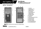
...2 optical drive eject button 3 optical drive panel 4 USB 2.0 connectors (2) 5 drive activity light 6 power button, power light 7 diagnostic lights (4) 8 headphone connector 9 microphone connector 10 link integrity light 11 padlock ring 12 cover-release latch, security cable slot 13 voltage selector switch 14 power ... 17 power supply diagnostic button 18 power supply diagnostic light NOTE: The voltage selector switch is available only on non-EPA power supplies. Models: DCSM1F, DCNE1F, and DCCY1F series March 2010 Dell™ OptiPlex™ 380 Setup and Features Information Mini Tower -
...2 optical drive eject button 3 optical drive panel 4 USB 2.0 connectors (2) 5 drive activity light 6 power button, power light 7 diagnostic lights (4) 8 headphone connector 9 microphone connector 10 link integrity light 11 padlock ring 12 cover-release latch, security cable slot 13 voltage selector switch 14 power ... 17 power supply diagnostic button 18 power supply diagnostic light NOTE: The voltage selector switch is available only on non-EPA power supplies. Models: DCSM1F, DCNE1F, and DCCY1F series March 2010 Dell™ OptiPlex™ 380 Setup and Features Information Mini Tower -
Setup and Features Information Tech Sheet
Page 2
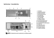
... on non-EPA power supplies. 1 optical drive 2 optical drive eject button 3 USB 2.0 connectors (2) 4 drive activity light 5 diagnostic lights (4) 6 power button, power light 7 link integrity light 8 microphone connector 9 headphone connector 10 power supply diagnostic button 11 power supply diagnostic light 12 voltage selector switch 13 cover-release latch, security cable slot 14 padlock ring 15 power...
... on non-EPA power supplies. 1 optical drive 2 optical drive eject button 3 USB 2.0 connectors (2) 4 drive activity light 5 diagnostic lights (4) 6 power button, power light 7 link integrity light 8 microphone connector 9 headphone connector 10 power supply diagnostic button 11 power supply diagnostic light 12 voltage selector switch 13 cover-release latch, security cable slot 14 padlock ring 15 power...
Setup and Features Information Tech Sheet
Page 3
... on non-EPA power supplies. 1 optical drive 2 optical drive eject button 3 USB 2.0 connectors (2) 4 power button, power light 5 link integrity light 6 diagnostic lights (4) 7 drive activity light 8 headphone connector 9 microphone connector 10 power supply diagnostic button 11 power supply diagnostic light 12 cover-release latch, security cable slot 13 padlock ring 14 voltage selector switch 15 power...
... on non-EPA power supplies. 1 optical drive 2 optical drive eject button 3 USB 2.0 connectors (2) 4 power button, power light 5 link integrity light 6 diagnostic lights (4) 7 drive activity light 8 headphone connector 9 microphone connector 10 power supply diagnostic button 11 power supply diagnostic light 12 cover-release latch, security cable slot 13 padlock ring 14 voltage selector switch 15 power...
Setup and Features Information Tech Sheet
Page 4
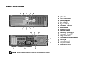
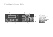
Mini Tower, Desktop, and Small Form Factor - Back Panel 1 9 8 2 3 4 7 1 parallel connector 2 link integrity light 5 3 network adapter connector 4 network activity light 5 line-out connector 6 line-in/microphone connector 7 USB 2.0 connectors (6) 6 8 VGA connector 9 serial connector
Mini Tower, Desktop, and Small Form Factor - Back Panel 1 9 8 2 3 4 7 1 parallel connector 2 link integrity light 5 3 network adapter connector 4 network activity light 5 line-out connector 6 line-in/microphone connector 7 USB 2.0 connectors (6) 6 8 VGA connector 9 serial connector
Setup and Features Information Tech Sheet
Page 7
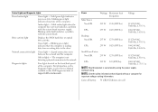
...drive or optical drive activity. A good connection exists between the network and the computer. Diagnostic lights Four lights located on state; Off (no light) - blinking green light indicates sleep state of the computer. NOTE: See the safety information that the computer is ...that shipped with your computer for important voltage-setting information. For information on the diagnostic lights, see the Service Manual available on the Dell Support website at support.dell.com/manuals. Coin-cell battery 3V CR2032 lithium coin cell Power Wattage Maximum heat dissipation...
...drive or optical drive activity. A good connection exists between the network and the computer. Diagnostic lights Four lights located on state; Off (no light) - blinking green light indicates sleep state of the computer. NOTE: See the safety information that the computer is ...that shipped with your computer for important voltage-setting information. For information on the diagnostic lights, see the Service Manual available on the Dell Support website at support.dell.com/manuals. Coin-cell battery 3V CR2032 lithium coin cell Power Wattage Maximum heat dissipation...
Guidebook
Page 4
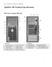
DELL™ OPTIPLEX™ 380 TECHNICAL GUIDEBOOK OptiPlex 380 Technical Specifications Mini Tower Computer (MT) View Front View 1 Optical Drive (optional) 6 Power Button, Power light 2 Optical Drive Eject Button 7 Diagnostic Lights (4) 3 Optical Drive Panel 8 Headphone Connector 4 USB 2.0 Connectors(2) 9 Microphone Connector 5 Hard Drive Activity Light 10 Network Connectivity Light Back View 11 Chassis Lock Loop 12 Cover Release Latch 13 Voltage...
DELL™ OPTIPLEX™ 380 TECHNICAL GUIDEBOOK OptiPlex 380 Technical Specifications Mini Tower Computer (MT) View Front View 1 Optical Drive (optional) 6 Power Button, Power light 2 Optical Drive Eject Button 7 Diagnostic Lights (4) 3 Optical Drive Panel 8 Headphone Connector 4 USB 2.0 Connectors(2) 9 Microphone Connector 5 Hard Drive Activity Light 10 Network Connectivity Light Back View 11 Chassis Lock Loop 12 Cover Release Latch 13 Voltage...
Guidebook
Page 5
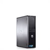
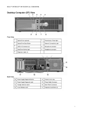
DELL™ OPTIPLEX™ 380 TECHNICAL GUIDEBOOK Desktop Computer (DT) View Front View 1 2 3 4 5 Optical Drive (optional) Optical Drive Eject Button USB 2.0 Connectors (2) Hard Drive Activity Light Diagnostic Lights (4) 6 Power button, Power light 7 Network Connectivity Light 8 Microphone connector 9 Headphone connector Back View 10 Power Supply Diagnostic Button 11 Power Supply Diagnostic Light 12 Voltage selection switch 13 Cover Release Latch 14 Chassis Lock Loop 15 Power Cable Connector 16 Back Panel Connectors 17 Expansion Card Slots (3) 5
DELL™ OPTIPLEX™ 380 TECHNICAL GUIDEBOOK Desktop Computer (DT) View Front View 1 2 3 4 5 Optical Drive (optional) Optical Drive Eject Button USB 2.0 Connectors (2) Hard Drive Activity Light Diagnostic Lights (4) 6 Power button, Power light 7 Network Connectivity Light 8 Microphone connector 9 Headphone connector Back View 10 Power Supply Diagnostic Button 11 Power Supply Diagnostic Light 12 Voltage selection switch 13 Cover Release Latch 14 Chassis Lock Loop 15 Power Cable Connector 16 Back Panel Connectors 17 Expansion Card Slots (3) 5
Guidebook
Page 6
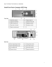
DELL™ OPTIPLEX™ 380 TECHNICAL GUIDEBOOK Small Form Factor Computer (SFF) View Front View 1 Optical Drive (optional) 2 Optical Drive Eject Button 3 USB 2.0 Connectors (2) 4 Power button, Power light 5 Network Connectivity Light 6 Diagnostic lights (4) 7 Hard Drive Activity Light 8 Headphone connector 9 Microphone connector Back View 10 Power Supply Diagnostic Button 11 Power Supply Diagnostic Light 12 Cover Release Latch 13 Chassis Lock Loop 14 Voltage Selection Switch 15 Power Cable Connector 16 Back Panel Connectors 17 Expansion Card Slots (3) 6
DELL™ OPTIPLEX™ 380 TECHNICAL GUIDEBOOK Small Form Factor Computer (SFF) View Front View 1 Optical Drive (optional) 2 Optical Drive Eject Button 3 USB 2.0 Connectors (2) 4 Power button, Power light 5 Network Connectivity Light 6 Diagnostic lights (4) 7 Hard Drive Activity Light 8 Headphone connector 9 Microphone connector Back View 10 Power Supply Diagnostic Button 11 Power Supply Diagnostic Light 12 Cover Release Latch 13 Chassis Lock Loop 14 Voltage Selection Switch 15 Power Cable Connector 16 Back Panel Connectors 17 Expansion Card Slots (3) 6
Service Manual
Page 2
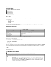
...Setup Menu Options NOTE: System Setup options may vary depending on your computer and may not appear in this key, press when the keyboard lights first flash. or right-arrow key, or +/- This menu is useful when you have trouble entering System Setup using this menu. l Memory... the following BIOS and System Setup options: l Bring up the diagnostics for the computer. Back to Contents Page System Setup Dell™ OptiPlex™ 380 Service Manual-Mini-Tower Boot Menu Navigation Keystrokes Entering System Setup System Setup Simulation System Setup Menu Options Boot Menu Press when ...
...Setup Menu Options NOTE: System Setup options may vary depending on your computer and may not appear in this key, press when the keyboard lights first flash. or right-arrow key, or +/- This menu is useful when you have trouble entering System Setup using this menu. l Memory... the following BIOS and System Setup options: l Bring up the diagnostics for the computer. Back to Contents Page System Setup Dell™ OptiPlex™ 380 Service Manual-Mini-Tower Boot Menu Navigation Keystrokes Entering System Setup System Setup Simulation System Setup Menu Options Boot Menu Press when ...
Service Manual
Page 11
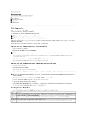
Back to Contents Page Diagnostics Dell™ OptiPlex™ 380 Service Manual-Desktop Dell Diagnostics Power Button Light Codes Beep Codes Diagnostic Lights Dell Diagnostics When to Use the Dell Diagnostics It is recommended that the device you want to test displays in the system setup program. 3. NOTE: The ... stating that you want to wait until you want . If you wait too long and the Windows logo appears, continue to run . Dell Diagnostics Main Menu 1. Run Express Test first to 20 minutes and requires no diagnostics utility partition has been found, run . NOTE: The...
Back to Contents Page Diagnostics Dell™ OptiPlex™ 380 Service Manual-Desktop Dell Diagnostics Power Button Light Codes Beep Codes Diagnostic Lights Dell Diagnostics When to Use the Dell Diagnostics It is recommended that the device you want to test displays in the system setup program. 3. NOTE: The ... stating that you want to wait until you want . If you wait too long and the Windows logo appears, continue to run . Dell Diagnostics Main Menu 1. Run Express Test first to 20 minutes and requires no diagnostics utility partition has been found, run . NOTE: The...
Service Manual
Page 12
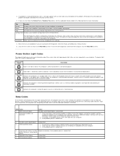
... error conditions encountered, error codes, and the problem description. Parameters The Dell Diagnostics obtains configuration information for the selected device. The computer is either turned off , light is encountered during the POST. Blinking Blue Indicates the computer is malfunctioning....of all modules without error. 2. Contact Dell. 1. If the problem persists, contact Dell. 5 Real-time clock failure. If the power light is blinking amber, the computer is receiving electrical power but legacy power light states are also supported in following table...
... error conditions encountered, error codes, and the problem description. Parameters The Dell Diagnostics obtains configuration information for the selected device. The computer is either turned off , light is encountered during the POST. Blinking Blue Indicates the computer is malfunctioning....of all modules without error. 2. Contact Dell. 1. If the problem persists, contact Dell. 5 Real-time clock failure. If the power light is blinking amber, the computer is receiving electrical power but legacy power light states are also supported in following table...
Service Manual
Page 13
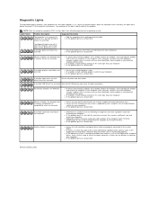
... of the same type into your computer). l If the problem persists, contact Dell . Reinstall all USB devices and check all power and data cables. l If the problem persists, contact Dell. Light Pattern Problem Description The computer is functioning properly. If the computer starts normally,...on the bank panel. l Reseat any installed graphics cards. l If the problem persists, contact Dell. Suggested Resolution l Plug the computer into a working graphics card into your computer has four lights labeled 1, 2, 3, and 4 on the screen identifying a problem with a device (such as ...
... of the same type into your computer). l If the problem persists, contact Dell . Reinstall all USB devices and check all power and data cables. l If the problem persists, contact Dell. Light Pattern Problem Description The computer is functioning properly. If the computer starts normally,...on the bank panel. l Reseat any installed graphics cards. l If the problem persists, contact Dell. Suggested Resolution l Plug the computer into a working graphics card into your computer has four lights labeled 1, 2, 3, and 4 on the screen identifying a problem with a device (such as ...


